www.rovingnetworks.com
Version 1.0r 9/21/2012
63
RN -W IFLYCR -U M
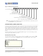
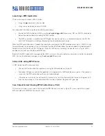
Figure 12. UDP Broadcast Packet Byte Format
NOTE:
To add sensor data to the UDP broadcast message you must enable the sensors using the sensor mask. The
set q sensor 0xff
command enables all sensors.
JOINING NETWORKS & MAKING CONNECTIONS
Configuring the module to make connections involves associating with an access point and opening a connection. Before
you can configure the module over the WiFi link you must associate the module with a network and program the network
settings. Therefore, the best method is to configure the module using the UART or over the air using ad hoc mode. This
section describes how to configure the module over the UART using the RS-232 connector or an evaluation board. For this
mode, open a terminal emulator on the COM port associated with the module. The default baud rate is 9,600, 8 bits, and
no parity.
To configure using ad hoc mode, refer to “Ad hoc Networking Mode” on page 77. Once in ad hoc mode, open a telnet
window using the IP address 169.254.1.1 port 2000.
Associate with an Access Point
From within the terminal window, put the module into command mode by typing
$$$
. The module responds with
CMD
,
indication that it is in command mode. Type
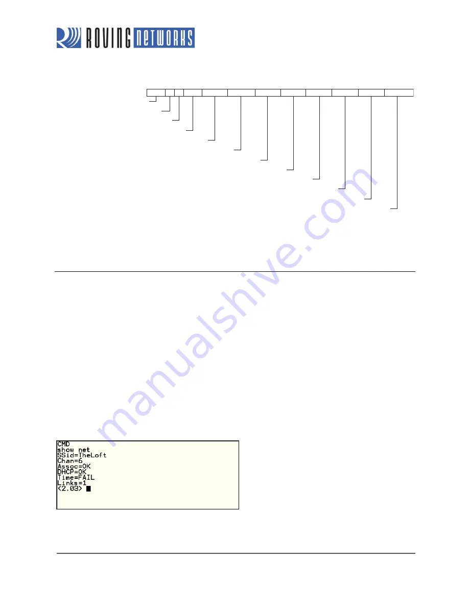
show net
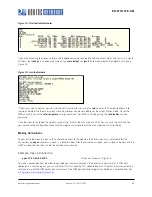
to display the current network settings as shown in Figure 13.
Figure 13. Display Current Network Settings
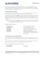
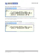
Find all available networks with the scan command as shown in Figure 14.
0 - 5 6 7 8 - 9 10 - 13 14 - 15 16 - 17 18 - 31 32 - 59 60 - 91 92 - 93 94 - 110
Programmable Device ID Set with
set option deviceid
<string>
(32 Bytes)
Version String with Date Code (26 Bytes)
ASCII Time (13 Bytes)
GPIO Pin Value (2 Bytes)
Access Point’s MAC Address (6 Bytes)
Channel (1 Byte)
RSSI (1 Byte)
Local TCP Port (2 Bytes)
Pin 20’s Battery Voltage in mV, e.g., 2755 (2 Bytes)
RTC Value, MSB to LSB (4 Bytes)
Position
Sensor 0 - 7 Voltage Readings Enabled with
set opt format
<
mask
>
(16 Bytes)
Boot Time in ms (2 Bytes)


