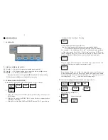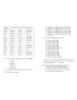
the displayed data will blink. If the indicator gets reasonable data, it will
calculate and store all parameters in EEPROM. And then it will auto-reset and
display all segments of LCD, full capacity… like power on again. If there’s an
error occurred in calibration, the scale will display “
CAL.Er
” and try to
repeat from step5. The scale will return to normal weighing mode.
======================================================
Ⅳ
. DISPLAY ADC CODE OR INPUT WORKING VOLTAGE VALUE
1. In normal weighing mode, press and hold down
ON/OFF/ZERO
and
HOLD/PRINT
key more than 3s, until ‘
codE
’ is shown, this means you have
been in display inner code mode; but first, the indicator will show the firmware
version “xx.xx.xx”. In this mode, you can examine the inner working voltage,
the stability of weighing system, the variety value of A/D data as per the loaded
weight.
NOTE:
1) The increment of A/D code for FS weight must be larger or equal to 2
times of selected display division-n; otherwise, the calibration cannot be
properly completed. Eg. The display division is 0.1kg. Load 100kg
standard weight on the platform, the increment of A/D code is at least 2x
100kg/0.1kg= 2x1000=2000. In this case, the scale can be calibrated.
Otherwise, smaller division needs to be chosen.
2) The data should be stable; otherwise, the calibration cannot properly
complete.
2. In this mode, you can calculate the proper ADC data at zero point by
examining the A/D data for loaded weight. If the ADC increase for full
capacity is NFS, the power-on zero range is set to Zp% FS (P12 setting) and
zero key range is set to Zk% FS (P13 setting). Then proper ADC data of zero
point is larger than (Zp%+ Zk%) x NFS.
ADC increase for full capacity (N
FS
) can be making out by: Load the weight
W on the platform, and the ADC increase for W weight is Nw. The ADC
increase for full capacity W
FS
is (N
FS
)= (Nw)x (W
FS
)/W
.
Negative value may be displayed because of error connect of loadcell or error
9
position of the zero-point potentiometer on PCB; however, the software only
deals with positive value. So, is you are the position of zero-point
potentiometer is error; adjust potentiometer’s position to make the ADC data
will be positive value and larger than (Zp%+ Zk%) x NFS. Normally the
indicator is factory-calibrated, and end users do not need this operation.
Below is the drawing of position of the zero-point potentiometer on PCB for
conference, decrease ADC data by rotating clockwise, and increase ADC data
by rotating counter-clockwise.
3. Press
UNIT
key to select displaying weight inner code or input the inner
working voltage value. When the “U x.xx” is displayed, the display digit is
voltage value, and the unit is V. The proper working power voltage is between
5V and 8V.
4. Press
TARE
key to display filtered or un-filtered weight A/D data; when
X
is
on, the data is filtered.
5. Press
ON/OFF/ZERO
key to exit this mode and return to normal weighing
mode.
========================================================
Ⅴ
. WORKING PARAMETER SETUP:
1. When scale is in normal weighing mode, press and hold down
10


