Input/Output mapping
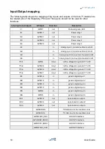
The following table shows the mapping of the inputs and outputs of the Iono Pi module into
the related pins of the Raspberry Pi board. These pins should not be used for other
functions.
Iono inputs and outputs
GPIO pin
Direction
Description
L1
GPIO7
out
On-board green LED
O1
GPIO17
out
Power relay 1
O2
GPIO27
out
Power relay 2
O3
GPIO22
out
Power relay 3
O4
GPIO23
out
Power relay 4
AI1
in
Analog input 1 (on terminal block) to A/D
AI2
in
Analog input 2 (on terminal block) to A/D
AI3
in
Analog input 3 (on board pin header) to A/D
AI4
in
Analog input 4 (on board pin header) to A/D
TTL1
GPIO4
in/out
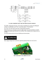
1-Wire, Wiegand or generic TTL I/O
TTL2
GPIO26
in/out
1-Wire, Wiegand or generic TTL I/O
TTL3
GPIO20
in/out
1-Wire, Wiegand or generic TTL I/O
TTL4
GPIO21
in/out
1-Wire, Wiegand or generic TTL I/O
DI1
GPIO16
in
generic digital input 1
DI2
GPIO19
in
generic digital input 2
DI3
GPIO13
in
generic digital input 3
DI4
GPIO12
in
generic digital input 4
DI5
GPIO6
in
generic digital input 5
DI6
GPIO5
in
generic digital input 6
OC1
GPIO18
out
open collector output 1
OC2
GPIO25
out
open collector output 2
OC3
GPIO24
out
open collector output 3
GPIO2/SDA
I
2
C SDA line for the real time clock
GPIO3/SCL
I
2
C SCL line for the real time clock
GPIO8/SPI_CE0
ADC SPI interface
GPIO9/SPI_MISO
ADC SPI interface
GPIO10/PI_MOSI
ADC SPI interface
GPIO11/SPI_CLK
ADC SPI interface
13
User Guide

