Smart Machine Smart Decision
4.11.
General Purpose Input/Output (GPIO)
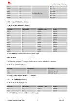
SIM2000S provides 2 GPIO pins. The output voltage level of the GPIO can be set by AT command “AT+ SGPIO”.
The input voltage level of the GPIO can also be read by AT command “AT+ SGPIO”. For more details, please
refer to
document [1]
.
Table 28: Pin definition of the GPIO
Pin name
Pin number
Reset state
GPIO33
67
Output, pull down
GPIO34
68
Output, pull up
4.12.
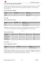
ADC
Table 29: Pin definition of the ADC
Pin name
Pin number
Description
ADC1
25
Analog voltage input
ADC2
36
Analog voltage input
SIM2000S provides two auxiliary ADC, which can be used to measure the voltage. User can use AT command
“AT+CADC” to read the voltage value. For details of this AT command, please refer to
document [1]
.
Table 30: ADC specification
Parameter
Min
Typ
Max
Unit
Voltage range
0
2.5
V
ADC Resolution
12
bits
Sampling rate
2.4
MHz
ADC precision
20
30
mV
4.13.
PWM
Table 31: Pin definition of the PWM
Pin name
Pin number
Description
PWM
35
Pulse Width Modulation
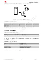
SIM2000S provides a PWM interface which can be used to drive a vibrator, and a backlight LED for display or
keyboard. PWM output frequency varies from 0 to 4.8MHz. AT command “AT + SPWM” is used to set the
output period and duty cycle of the PWM. For details, please refer to
document [1].
SIM2000S_Hardware_Design_V1.00
40
2014-02-27

