Somat eDAQ
lite
142
I2773-4.
4
en
Application Note: Load-Life Fatigue Damage
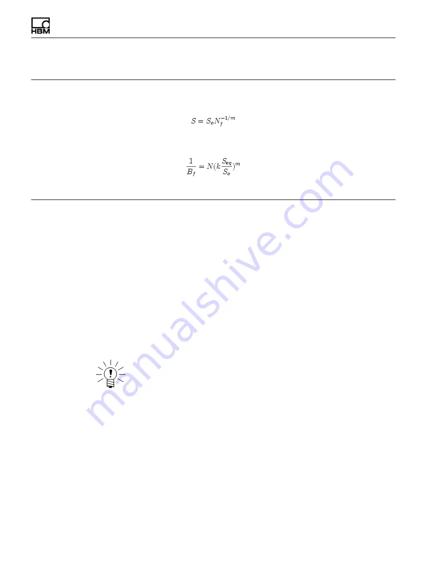
If the input channel is a linear function of load, the outputs of this channel can translate to a simple load-life fatigue damage
assessment for the test run. For example, assuming that a load-life relationship is given by
where,
N
f
is the constant load range cycles to failure,
S
o
is the load range when
N
f
equals 1 and
m
is the damage slope.
Assuming that S equals the product of some coefficient
k
and the input channel, it follows that the fractional fatigue damage
per block (i.e., per test run),
1/B
f
, is given by
Note that load-life relationships are most typically defined in terms of load amplitude versus cycles to failure, instead of in
terms of load range versus cycles to failure as in the above example.
7.2.10
Fatigue Damage
The Fatigue Damage channel generates an output stream of fatigue damage for the
selected input channel. The fatigue damage computations are based on the selected
fatigue damage model, material parameters and on optional input and output scaling
parameters.
Scaling the input channel can be useful, for example, in converting transducer data in
microstrain units to dimensionless strain units required for the fatigue processing
models. TCE processes the optionally scaled input channel on a point-by-point basis
through a rainflow cycle counter using the user-defined hysteresis value for peak
picking. For each closed cycle, the computed fatigue damage is added to the running
sum of cumulative fatigue damage based on the user-selected fatigue damage model.
For each output sample, the residual peak-valley sequence is processed through the
rainflow cycle counter to account for the additional accumulated fatigue damage. The
output values are effectively scaled based on the user-selected damage units option.
NOTE
The use of the scaling options does not result in any processing overhead because of
the way that these parameters are integrated into the fatigue damage solvers.
For more information on the data processing algorithms used, see
Input Channel
The input channel data type must be 32-bit float.
Output Data Type
The output channel data type is 32-bit float.
Scale Factor
Specify the desired scaling factor typically used to convert the input channel data into
the proper units based on the damage model. For example, the scale factor converts
input channel data in microstrain units to dimensionless strain units when using the
strain-life damage model.
HBM: public
Summary of Contents for eDAQlite
Page 1: ...User Manual English Deutsch Espanol I2773 4 4 en HBM public Somat eDAQlite with TCE Software ...
Page 2: ...Somat eDAQlite 2 I2773 4 4 en HBM public ...
Page 16: ...Somat eDAQlite 16 I2773 4 4 en HBM public ...
Page 22: ...Somat eDAQlite 22 I2773 4 4 en HBM public ...
Page 88: ...Somat eDAQlite 88 I2773 4 4 en HBM public ...
Page 106: ...Somat eDAQlite 106 I2773 4 4 en HBM public ...
Page 128: ...Somat eDAQlite 128 I2773 4 4 en HBM public ...
Page 190: ...Somat eDAQlite 190 I2773 4 4 en HBM public ...
Page 202: ...Somat eDAQlite 202 I2773 4 4 en HBM public ...
Page 222: ...Somat eDAQlite 222 I2773 4 4 en HBM public ...
Page 224: ...Somat eDAQlite 224 I2773 4 4 en HBM public ...


