Chapter 2
Reserving DRAM for SX Accelerated Applications
5
Configuring SXDRAM
This section lists the steps to follow in order to configure SXDRAM. It also discusses
the constraints imposed by the system software and hardware. It is essential that
you understand the system memory map before you configure SXDRAM.
Note that there are some key differences in the way memory is arranged on the
SPARCstation 10SX and the SPARCstation 20:
■
The physical sequence of slots is different
■
The slots that can use VSIMMs are different
Information specific to the SPARCstation 20 is provided in Section “Memory Bank
Layout on the SPARCstation 20” on page 8. To plan SXDRAM configurations for
those systems, take this information into account when applying the principles
explained in the material covering the SPARCstation 10SX.
Memory Bank Layout on the SPARCstation 10SX
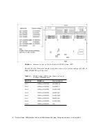
There are two memory banks on a SPARCstation 10SX. Bank 0 is comprised of slots
0, 1, 2, and 3. Bank 1 is comprised of slots 4, 5, 6, and 7. These 8 slots are available
for configuring memory on the SPARCstation 10SX. Each bank of memory can map
256 MByte of physical address space. Each slot in each memory bank maps 64 MByte
of physical address space.
The beginning physical address for bank 0 is 0. For bank 1, it is 0x10000000.
Slots 4 must be configured with a VSIMM; slot 5 may be configured with either a
DSIMM or a VSIMM (CG14). The SPARCstation 10SX supports 16 MByte and 64
MByte DSIMMs, and 4 MByte and 8 MByte VSIMMs. Each slot maps 64 MByte of
physical address space regardless of the size and type of SIMM that is configured in
the slot.

