S50 Hardware User Guide
1VV0301505 Rev. 3
Page 21 of 60
2021-05-05
Not Subject to NDA
4.6.
SPI Serial Peripheral Interface
Functionality is defined project specific in the firmware used.
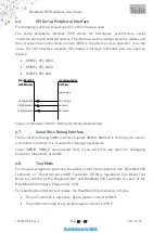
The serial peripheral interface (SPI) allows for full-duplex, synchronous, serial
communication with external devices. The interface can be configured as the master and
then provides the communication clock (SCK) to the external slave device(s), or as the
slave. The SPI Interface supports SPI-modes 0 through 3. Module pins are used as
follows:
•
GPIO[2]: SPI-MOSI
•
GPIO[5]: SPI-MISO
•
GPIO[8]: SPI-SCK
GPIO[8]/SPI-SCK
GPIO[2]/SPI-MOSI
S50
E-2
SPI-Master
connected device
SPI-Slave
GPIO[5]/SPI-MISO
D-1
F-2
SCK, SPI_CLK
SDI, MOSI
SDO, MISO
typical signals:
Figure 12: S50 SPI Interface (Example: Master Mode)
4.7.
Serial Wire Debug Interface
The Serial Wire Debug (SWD) interface (signals SWDIO, SWCLK) is normally not used in
a customer’s product. It is reserved for debugging purposes.
Leave SWDIO, SWCLK unconnected. Only if you intend to use them for debugging
purposes, make them available.
4.8.
Test Mode
For regulatory approval purposes,
the ability of test mode operation like “
S50
Testmode
” or “Direct two wire UART Testmode” (DTM) is mandatory. The Direct Test
Mode (as defined by the Bluetooth SIG) and S50 Testmode are part of the
S50 firmware. Please refer to [6].
For enabling the different test modes, the S50 provides two IO pins.
•
The pin Testmode is low active. Active means connect to GND.
•
The pin Boot0 is high active. Active means connect to VSUP.

