Self-Balancing Robot
User Guide
23
www.terasic.com
July 12, 2018
located in \Demonstrations\BAL_CAR_Nios_Code\IP\sonic_distance\sonic_distance.v
⚫
⚫
I
I
P
P
s
s
y
y
m
m
b
b
o
o
l
l
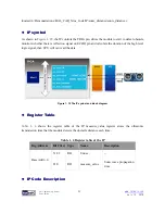
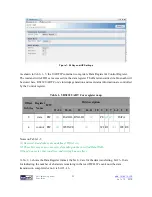
As shown in
Figure 1- 19
, the IP controls the TRIG pin, drives the module to start to detect obstacle,
monitors whether there is reflection signal on ECHO pin and calculate the duration of the high level
logic signal, then CPU will can read the data.
Figure 1- 19 The IP symbol and block diagram
⚫
⚫
R
R
e
e
g
g
i
i
s
s
t
t
e
e
r
r
T
T
a
a
b
b
l
l
e
e
Table 1- 4
shows the register table of the IP. measure_value register stores the ultrasonic
transmission time that the module detects the obstacle distance each time.
Table 1- 4 Register table of the IP
Reg Address
Bit Filed Type
Name
Description
Base Addr + 0
31:22
RO
Unuse
--
21:0
RO
measure_value
Sonic wave propagation
time
⚫
⚫
I
I
P
P
C
C
o
o
d
d
e
e
D
D
e
e
s
s
c
c
r
r
i
i
p
p
t
t
i
i
o
o
n
n


