Self-Balancing Robot
User Guide
3
www.terasic.com
July 12, 2018
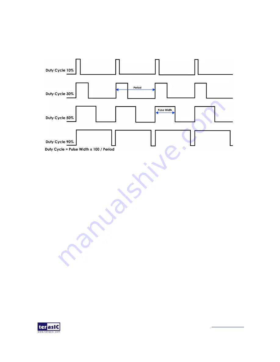
As shown in
Figure 1- 2
, the motor speed is faster while the PWM signal Duty Cycle is higher
(Which means the ratio of the high logic positive pulse duration to the total pulse period is higher).
Figure 1- 2 The diagram of different Duty Cycle
The maximum PWM frequency that TB6612FNG provides is 100KHz. For the Self-Balancing
Robot, the PWM frequency is set as 7.14KHz.
◼
◼
E
E
x
x
a
a
m
m
p
p
l
l
e
e
D
D
e
e
s
s
c
c
r
r
i
i
p
p
t
t
i
i
o
o
n
n
Motor control IP TERASIC_DC_MOTOR_PWM.v is provided in the robot demo code. In this
demo, it is packed as Qsys component and used to control the right and left motor. User can find the
TERASIC_DC_MOTOR_PWM.v
file
in
the
robot
system
CD:
Demonstrations\BAL_CAR_Nios_Code\IP\TERASIC_DC_MOTOR_PWM
⚫
⚫
I
I
P
P
S
S
y
y
m
m
b
b
o
o
l
l
Figure 1- 3
shows the symbol of TERASIC_DC_MOTOR_PWM.v and its block diagram. The
main outputs are DC_MOTOR_IN1, DC_MOTOR_IN2 and PWM, others are Avalon interface
signals. The DC_MOTOR_IN1 and DC_MOTOR_IN2 are the control signals that can control the
motor rotation direction and stopping, which has been described in previous section. PWM control
signal is responsible for controlling the motor speed.


