Self-Balancing Robot
User Guide
31
www.terasic.com
July 12, 2018
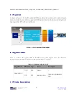
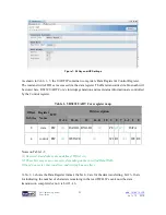
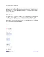
Figure 1- 24 Qsys uart IP Settings
As shown in
Table 1- 5
, the UART IP contains two registers: Data Register & Control Register.
The read and write FIFOs are accessed via the data register. The Data transmitted via bluetooth will
be stored here. RS232 UART Core’s interrupt generation and read-status information are controlled
by the Control register.
Table 1- 5 RS232 UART Core register map
Offset
in bytes
Register
Name
R/W
Bit description
31..24
23..16
15
14..11 10 9
8 7 6..2 1
0
0
data
RW
(1)
RAVAIL RVALID
(1)
PE
(2)
(2)
DATA
4
control RW
(1)
WSPACE
(1)
WI RI
(1)
WE RE
Notes on Table 1-5
(1) Reserved. Read values are undefined. Write zero.
(2) These bits may or may not exist, depending on the specified DataWidth.
If they do not exist, they read zero and writing has no effect.
Table 1- 6
shows the Data Register format, the bit 8~0 are for the data transferring, bit 23~16 are
for indicating the number of characters remaining in the read FIFO. We can know the data
transmission completed or not via bit 23~16.


