Self-Balancing Robot
User Guide
2
www.terasic.com
July 12, 2018
signals output from FPGA should be opposite to the logic described in the TB6612FNG datasheet.
◼
◼
C
C
o
o
n
n
t
t
r
r
o
o
l
l
R
R
o
o
t
t
a
a
t
t
i
i
o
o
n
n
D
D
i
i
r
r
e
e
c
c
t
t
i
i
o
o
n
n
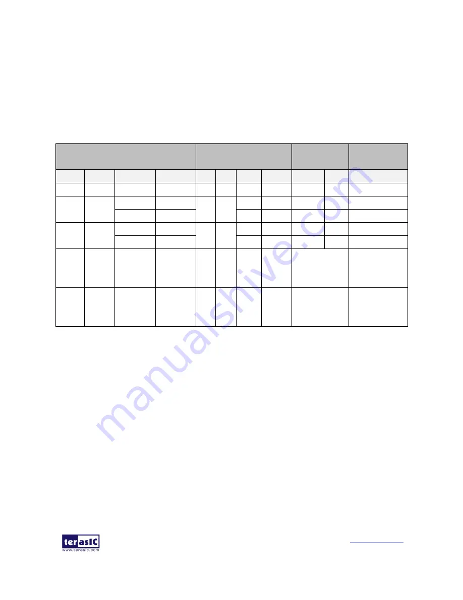
Table 1- 1
lists the TB6612FNG control function.
Table 1- 1 TB6612FNG Control Function
⚫
Control the logic value for IN1 and IN2 can drive the motor to counterclockwise rotation (IN1
= 0; IN2 = 1) or clockwise rotation (IN1 = 1; IN2 = 0).
⚫
The motor will stop rotation when logics of both the two control signals (IN1 and IN2) are 0.
⚫
STBY is equal to Chip Enable function. The motor will stop and wait for new command when
STBY logic is 0.
In summary, user can easily change the motor rotation direction via controlling the IN1 and IN2
logic value.
◼
◼
C
C
o
o
n
n
t
t
r
r
o
o
l
l
R
R
o
o
t
t
a
a
t
t
i
i
o
o
n
n
S
S
p
p
e
e
e
e
d
d
The motor speed of the motors can be controlled by controlling the Duty Cycle of the PWM signal.
FPGA Control Output
Driver Input
Driver
Output
Modes
description
MTRX_P
MTRX_N
MTR_PWMX
MTRX_STBY
IN1
IN2
PWM
STBY
O1
O2
--
0
0
1/0
0
1
1
1/0
1
0
0
Short brake
1
0
1
0
0
1
1
1
0
1
CCW
0
0
0
1
0
0
Short brake
0
1
1
0
1
0
1
1
1
0
CW
0
0
0
1
0
0
Short brake
1
1
1
0
0
0
1
1
OFF
(High
Impedance)
Stop
0/1
0/1
1/0
1
1/0
1/0
1/0
0
OFF
(High
Impedance)
Standby


