User Manual for Machine Vision Cameras
100
Figure 11
-
14
PWM mode parameter control
11.5
General Purpose I/O configuration
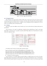
(This is for I3 series only)The camera with the hardware version number V2.0 and above has a configurable GPIO port,
as shown in Figure 11
15, in the demo, enter the "IO Config" dialog, select the "Line Select" to be GPIO0 and then click the
"GPIO Mode" to configure the input or output.
Figure 11
-
15
GPIO configuration
The following is the API code to configure the GPIO input and output direction:
Toupcam_IoControl(m_hCam, index, TOUPCAM_IOCONTROLTYPE_SET_GPIODIR, val, NULL);
11.6
Input signal
11.6.1
Signal debouncer
Because the external trigger input signal of the camera may have burr, if it goes directly into the internal logic of the
camera, it will cause false trigger. The input trigger signal should be debounced. In addition, the effective pulse width of the
trigger signal inputted by the user should be greater than the debouncer time, otherwise the trigger signal will be ignored.
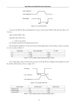
The timing is shown in Figure 11
16. If the effective pulse width of Trigger_in1 is less than the debouncer time, the trigger
signal will be ignored.
Figure 11
-
16
Signal debounce timing
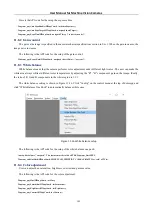
As shown in Figure 11
17, in
democpp
, enter the "IO Config" dialog, click "Line Select" to select the input line and
then set the debouncer time at "Debounce Time" in the range of 0≤20000 in microseconds.

