EVK-NINA-B4 - User guide
UBX-19054587 - R04
Interfaces and peripherals
Page 32 of 40
C1 - Public
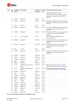
Connector
annotation
Pin
number
Schematic net name
nRF52 pin Description
11
N/C
-
Not connected
12
TRACE_CLK/GPIO_45
P0.07
Parallell trace clock signal
13
N/C
-
Not connected
14
TRACE_D0/SWO/
GPIO_8
P1.00
Serial trace data signal / Parallell trace data signal
15
GND
GND
Ground
16
TRACE_D1/GPIO_46
P0.12
Parallell trace data signal
17
GND
GND
Ground
18
TRACE_D2/GPIO_32
P0.11
Parallell trace data signal
19
GND
GND
Ground
20
TRACE_D3/GPIO_33
P1.09
Parallell trace data signal
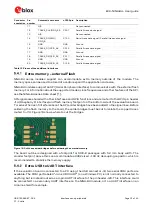
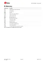
Table 15: Pinout of the additional interfaces
Extra memory
–
external Flash
NINA-B4 series modules support can accommodate extra memory outside of the module. The
memory space can be used to store data and/or expand the application code size.
NINA-B4 modules support an SPI (Serial Peripheral Interface) to communicate with the external flash
memory. For information about the supported modes, clock frequencies and other features of the SPI,
see the NINA-B4 series Data sheet [1].
SPI signals are shared with other interfaces and GPIO functions and are routed to the GPIO pin header
J14 (Raspberry Pi interface) and flash memory footprint on the bottom side of the evaluation board.
To reduce the risk of interference on the SPI, solder bridges have been added to the signal lines. Before
soldering the flash memory to the board, the solder bridges must be cut to isolate the copper traces
routed to J14. Figure 19 shows where to cut the bridges.
Figure 19: Cut these solder bridges before soldering the external memory
The board outline is designed with a footprint for SOIC-8 packages with 5.3 mm body width. The
smaller footprint above this can accommodate a 0402 sized ~100 nF decoupling capacitor, which is
recommended to stabilize the memory supply.
Extra USB to UART interface
If the evaluation board is connected to a PC using the USB connector J8, two serial COM ports are
available. The COM port labeled
“
JLink CDC
UART”
(on a Windows PC) is not normally connected to
anything but is instead routed as a 4-pin UART interface to the pin header J20. This interface could
be connected to a secondary UART interface on the NINA-B4 module, or to a UART interface on an
Arduino shield for example.


