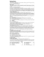


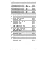

CV 38
Function key F4
32
Bit 5
Function output A4 (SUSI/logic)
32
CV 39
Function key F5
64
Bit 6
Rangiergang
64
CV 40
Function key F6
128
Bit 7
Starting/braking deceleration
128
CV 41
Function key F7
0
CV 42
Function key F8
0
CV 43
Function key F9
0
CV 44
Function key F10
0
CV 45
Function key F11
0
CV 46
Function key F12
0
Example 1:
The rear light output should only be switched with the function key F5.
The CV to be programmed is the CV39 for the function key F5 in which the value 2 (rear light output) is programmed. So that
the rear light output is no longer switched backwards in the direction of travel via the function key F0, the CV34 for the function
key F0 in the direction of travel must also be programmed backwards to the value 0.
Example 2:
The function output A1 and the shunting ring should be switched together with the function key F10. The CV to be
programmed is the CV44 for the function key F10. In this CV44 the value 4 (function output A1) plus the value 64 (shunting
gear), ie the value 68 is programmed. So that the function output A1 is no longer switched via the function key F1 and the
shunting lever no longer via the function key F5, the CVs 35 for the function key F1 and 39 for the function key F5 must also
be programmed to the value 0.
Turn off front and rear train lights
(CV96 = 0)
In CV107 (front) and CV108 (rear), the numbers of the special functions 1 - 12 can be entered, which switch off the white and
red lights front or rear. Furthermore, it can be entered here to which function outputs A1 and A2 the red train terminal lighting
is connected in each case.
The function numbers entered here must be set via the function mapping so that they do not switch on other outputs.
Furthermore, it must be ensured that the outputs used for the red lighting are not switched off or switched off via the function
mapping of other function keys. the Function Mapping CV of the F-keys used here must be set to zero. In order for the
switching off of the light to work properly, both CVs 107 and 108 must always be programmed as desired. If one of the CVs
107 or 108 is programmed with the value 0, the function is considered deactivated.
The value for programming the CVs 107 and 108 consists of two conditions. On the one hand, to which the outputs A1 or A2
the switched off lighting is connected and on the other hand, with which function key F1 to F12 the lighting is to be switched.
Since a CV can only be described with a value, these conditions are summarized into a value according to the following
scheme:
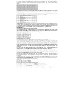
Light assignment: A0v = white light front, A0h = white light rear
CV107 for red front lighting
CV108 for red rear lighting
Calculation: output * 16 + function key
Example
: The red lighting at the front should be connected to A1 and switched with F5.
CV107=1*16+5=21
The rear red light should be connected to A2 and switched with F6.
CV108=2*16+6=38
Switch off function outputs depending on the
direction of travel (CV96 = 0)
In the CVs 113 (forward direction) and 114 (backward direction) it can be defined which function output A1 - A4 (A3 & A4 logic
on SUSI, CV50 bit 4 = 1) should be switched off. If such an output is switched on via a wireless button, it is automatically
switched off in the desired direction of travel.
CV113 = 2 -> A1 forward from CV113 = 4 -> A2 forward from CV113 = 8 -> A3 forward from CV113 = 16 -> A4 forward from
CV114 = 2 -> A1 backwards from CV114 = 4 -> A2 backwards from CV114 = 8 -> A3 backwards from CV114 = 16 -> A4 backwards from
A combination (sum of the individual values) is possible.
Simple and advanced function mapping
The following settings of the decoder are possible with the simple (CV96 = 0) and with the extended (CV96 = 1) function
mapping.
Dimming of light and function outputs
The light and function outputs A1 & A2 can be set to any dimming. These settings are stored in CVs 116 (light), 117 (A1) and
118 (A2).
Soft fade-in and fade-out of light and function outputs
If the output is switched on or off, it is softly switched on or off.
In the CV186 it can be defined which output should receive this glare function. CV186 = 1 -> light outputs with glare function,
CV186 = 2 -> A1 with glare function, CV186 = 4 -> A2 with glare function. A combination (sum of the individual values) is of
course also possible here.
The setting of the CV187 specifies how fast the glare function should work. The step size is CV value * 1ms.
Flashing of light and function outputs
The locomotive decoder has a flashing generator, which can be assigned to the outputs. Both the switch-on time and the
switch-off time of the flashing generator are separately adjustable.
In the CV109 you can define which output should use the flashing generator. Furthermore, it can be defined in the CV110,
which output should use the flashing generator with 180° rotated phase position. For example, a changeover line can be
realized.
CV109 = 1 -> light outputs flash, CV109 = 2 -> A1 flashes, CV109 = 4 -> A2 flashes. A combination (sum of the individual
values) is of course possible.
CV110 = 1 -> Light outputs flash with turned phase, CV110 = 2 -> A1 flashes with turned phase, CV110 = 4 -> A2 flashes with
turned phase. Of course, a combination is also possible here.
In the CV111 the switch-on time is adjustable in 100ms steps and in the CV112 the switch-off time in 100ms steps.
Energy saving lamp effect when switching on the light and function outputs
When an energy-saving lamp is switched on, it first produces a basic brightness before it slowly reaches the maximum
brightness. This effect can be assigned to the outputs of the decoder as follows. CV183 = 1 -> effect for light outputs, CV183
= 2 -> effect for A1, CV183 = 4 -> effect for A2.
A combination (sum of the individual values) is of course also possible here.
The basic brightness is adjustable via the CV184. The setting of the CV185 specifies how fast the final value of the brightness
(PWM1 in CVs 116 - 118) should be reached. The step size is CV value * 5ms.
Switching on effect of a neon tube / fluorescent lamp
The switching effect of a defective neon tube can also be output at the light and function outputs. This effect consists of an
adjustable, maximum number of flashes (random one flash up to the maximum number of flashes) and an adjustable flash
time, so how fast the flashes should follow each other.
CV188 = 1 -> effect for light outputs, CV188 = 2 -> effect for A1, CV188 = 4 -> effect for A2.
A combination (sum of the individual values) is of course also possible here.
The flash time is set via the CV 189 in 5ms steps. The maximum number of flashes in CV 190.


