Manual BG41/BG42/BG43
Software
Rev. 99/49
4-37
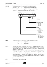
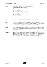
ANZW
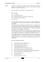
Display word. The display word contains one word. Status bits are filed in the
right byte. An error number is filed in the left byte, if the idenfication “finished
with an error“ appears in the right byte.
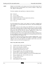
The status identifiers in the right byte are structured as follows:
Bit 0: Not used
Bit 1: Job running
Bit 2: Finished without an error
Bit 3: Finished with an error,
→
Error number in the left byte
Bit 4: Interface momentarily occupied
Bit 5-7:Not used
The data handling block hands over at the loading of the interface building block
only enough bytes, as were parametrized as block size on the data handling block
SYNCHRON.
For these reasons the data handling block SEND may have to be loaded several
times, in order to transmit a complete telegram to the interface building block. If
the data handling block has one or more data blocks, but has not yet transmitted
the last data block to the interface building block, bit 1 is placed in the right byte
of the display word as identifier for “job running.“
If all data blocks have correctly been received by the interface building block and
the receiver does not report an error, the data handling block SEND places the Bit
2 in the right byte of the display word as identifier for “finished without an error.“
If the telegram from the interface building block has not been received, e.g.
receiver does not answer, or when the receiver reports an error, the data handling
block SEND places the bit 3 in the right byte of the display word as identifier for
“finished with an error.“ In this case an error number is in the left byte of the
display word.
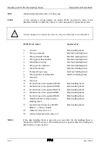
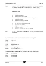
Error code, delivered by ANZW:
05
Telegram header contains invalid target type
09
Receiver does not answer with DLE
14
Wrong telegram header (the first 2 bytes)
15
Transmission terminated by receiver
16
Wrong command code 2. letter (invalid target area)
20
DB error (DB0 used, DB too long, DB not available)
21
Receiver does not answer within QVZ (Timeout on SSM building block)
22
Wrong command code 1. letter (invalid source area)
23
QVZ in connection set-up
50
Coordination flag set
52
Data length greater than 128 bytes
Summary of Contents for SSM-BG41
Page 2: ...Lerrzeichen...
Page 8: ...Contents Manual BG41 BG42 BG43 iv Rev 99 49...
Page 10: ......
Page 16: ......
Page 26: ...Firmware s memory distribution Manual BG41 BG42 BG43 2 10 Rev 99 49...
Page 28: ......
Page 53: ...Manual BG41 BG42 BG43 Interface modules Rev 99 49 3 25 3 2 7 2 Data flow Fig 3 26 Data flow...
Page 114: ...Functional description and allocation of terminal pins Manual BG41 BG42 BG43 3 86 Rev 99 49...
Page 116: ......
Page 215: ...Manual BG41 BG42 BG43 Software Rev 99 49 4 99 Month 06h Year 95h Weekday Tuesday 02h...
Page 222: ...Application of interfaces without data handling blocks Manual BG41 BG42 BG43 4 106 Rev 99 49...
Page 224: ......
Page 258: ...Structure guidelines Manual BG41 BG42 BG43 5 34 Rev 99 49...
Page 260: ......
Page 274: ...Overview cycle load Manual BG41 BG42 BG43 6 14 Rev 99 49...
Page 275: ...Appendix A List of figures A 1 B Index of tables B 1 C Index C 1...
Page 276: ......
Page 280: ...List of figures Manual BG41 BG42 BG43 A 4 Rev 99 49...

