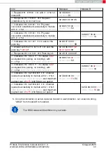


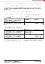
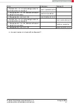
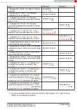

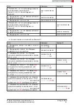
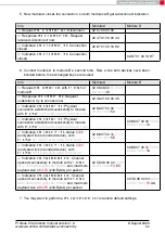


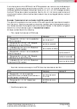

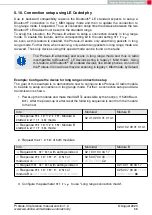


Info
Module A
Module B
⇐
Reset both modules using
pin,
02 41 02 00 01 01 41
02 41 02 00 01 01 41
⇒
Configure
using
to "beacon rx enabled, no filter"
02 11 02 00 0E 01
1E
⇐
from module B
02 51 01 00 00 52
⇐
Module B reset such that the change in the
user setting takes effect (
02 41 02 00 01 01 41
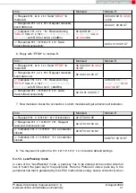
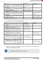
⇒
Activate scanning on module B
02 09 00 00 0B
⇐
Response
02 49 01 00 00 4A
⇒
, content "
Hallo
"
02 0C 05 00
48 61
6C 6C 6F
4D
⇐
02 4C 01 00 00 4F
⇐
receiving multiple
02 8C 0C 00 02 00
00 DA 18 00 B5
48
61 6C 6C 6F
B1 02
8C 0C 00
02 00 00
DA 18 00
B1 48 61
6C 6C 6F B5
..
.
..
.
..
.
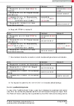
⇒
Deactivate scanning on module B,
02 0A 00 00 08
⇐
Response
02 4A 01 00 00 49
⇒
Reset module A (disable sending beacons),
02 00 00 00 02
⇐
Response
02 40 01 00 00 43
⇐
Response
02 41 02 00 01 01 41
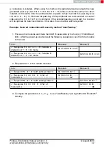
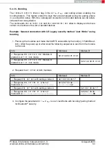
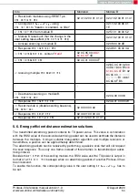
5.6. Energy-efficient distance estimation solutions
The transmitted advertising packet contains its TX power value. This value in combination
with the RSSI value of the received advertising packet can be used to estimate the distance
between the modules. Using a suitable triangulation algorithm and multiple receivers or
transmitters, a position can be approximately determined.
The advertising packets can be received by performing a passive scan that will not request
the scan response. Thus only one frame, instead of three frames, is transmitted per adver-
tising interval.
Besides the
of the sending module, the RSSI value and the TX power is output in
format of a
message when an advertising packet of another Proteus-III has
been received.
To enable this function, the corresponding value in the user setting
has to
be set.
Proteus-III reference manual version 1.3
© August 2020
www.we-online.com/wireless-connectivity
54


