24
J DF 3 0 0 |
FI EL D I N D I C ATO R | O I/J D F 3 0 0 - EN R E V. B
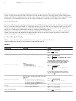
. . .HMI TB Mapping
Idx
Parameter
Description / Range / Selections / Notes
31
IN8_SUBTAG
Default string:
“Input 7”
32
IN8_UNIT CODE
“********”
33
IN_ENABLED
Each IN has an associated bit in order to
enable disable its use
Bit 7 = IN8 …………………Bit 0 = IN1
Bit x = 0 – Input not used/enabled
Bit x = 1 – Input used/enabled
Default = 00000001 = only IN1 enabled
34
IN_SEQUENCE
1:
OFF (default)
When IN_SEQUENCE = ON, the MAO Channel must switch
to the next ENABLED Inputs evaluating the IN_ENABLED
bit corresponding to the channel number
2:
ON
35
SEQUENCE_SPEED
1:
FAST (default)
When IN_SEQUENCE = ON, this parameter specify at which
rate chance the IN selection. Every 6 seconds when FAST
and 12 seconds when SLOW.
2:
SLOW
36
NUM_STATUS_ENA
1:
OFF (default)
Quality Status text view
2:
ON
Status Byte decimal number view
37
SQUAWK
1:
Disabled (default)
Squawk = off
2:
Enabled
Squawk blinking
3:
Squawk once
Blink for 2 seconds
38
PWR_ON_COUNT
Number of power cycle
39
TOT_WORK_TIME
Counter of how much time the device has been powered on expressed in days/hours/mins.
10 Control Application Process (CAP) Blocks
Multiple Analog Output Function Block (MAO)
Overview
The MAO block makes available to the I/O subsystem its eight input parameters IN_1/8.
This function block keeps the fault state features specified for the AO block. It includes option to hold the last value or a preset
value when in Fault State, individual preset values for each point, besides a delay time to go into the Fault State.
The actual mode will be LO only due to the resource block (SET_FSTATE parameter). If an input parameter has a bad status, that
parameter will be in Fault State, but the mode calculation of the block will not be affected.
The FSTATE_STATUS parameter shows that points are in Fault State.
The MAO block does not support back calculation, or the Cas mode.
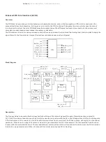
Block Diagram
Description
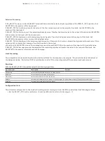
The Channel selects the input to be propagated in output at the connected transducer block.
IN_1
IN_2
IN_3
IN_4
IN_5
IN_6
IN_7
IN_8
BLOCK
ALGORITHM
OUTPUT SNAP
TO
TRANSDUCER
BLOCK INPUTS
CHANNEL

