ACCES I/O Products, Inc.
MADE IN THE USA
mPCIe-DIO-24S Family Manual
4
Rev B2d
C
HAPTER
7:
S
OFTWARE
I
NTERFACE
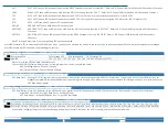
Register Overview
Register
Offset [hex]
Read
/Write
Register Name
Register Description
Note: All registers 4-68 must be accessed as 32-bits. Only +0 and +1 are 8-bits
+0 RW
Reset
Board and Feature Reset command
+1 W/R
IRQ Enable / Status
IRQ Latch Clear bits and IRQ Enable Control bits / IRQ Latch Status and IRQ Enable Status
+4 W
DAC Control
DAC (LTC1664) Command Register bits
+C R
ADC Base Clock
Frequency of the ADC Sequencer Base Clock (Hz) used to calculate the ADC Rate Divisor for desired conversion rates
+10 W/R
ADC Rate Divisor
ADC Conversion Rate = ADC Base Clock / ADC Rate Divisor (this register)
+14 W/R
ADC Rate Divisor #2
Reserved
+18 W/R
ADC ADV Sequence Gain
Each nybble controls the gain code (input range) of the respective ADC channel (0-7)
+1C W/R
ADC ADV Sequence Gain #2 Each nybble controls the gain code (input range) of the respective ADC channel (8-15)
+20 W/R
ADC FAF Threshold
ADC FIFO Almost Full Threshold, can be enabled to generate IRQs when the threshold amount of ADC data is available in the FIFO
+28 R
ADC FIFO Count
ADC FIFO Depth: read to determine how much data is available in the FIFO
+30 R
ADC FIFO Data
ADC FIFO
+38 W/R
ADC Control
ADAS3022 and ADC Control bits
+44 W/R
DIO Data
2-bits of DIO Data
+48 W/R
DIO Control
Digital Secondary Function enable bits and direction control for each I/O Group (DIO 1 and DIO 0)
+68 R
Revision
FPGA code revision
All these registers can be operated from any operating system using any programming language, using either no driver at all (kernel mode, Linux ioperm(3), DOS, etc.) or using one of the
ACCES provided drivers (AIOWDM [for Windows], APCI [for Linux & OSX]), or using any 3
rd
party APIs such as provided with Real-Time OSes. Addresses not explicitly documented are
reserved and should not be accessed.
REGISTER DETAILS
Register bits labeled UNUSED or RSV are reserved and should be cleared to zero in all write operations and ignored in all read operations.
Reset, 0 of 32-bit Memory BAR[1] Write-Only 8-bits only
bit D7
D6
D5
D4
D3
D2
D1
D0
Name RESET
Write the byte 0xFF to +0 to reset the board to the power-up state.
IRQ Enable/Clear and Status, 1 of 32-bit Memory BAR[1]Read/Write
PRELIMINARY
bit D31
D30 … D24
D23 D22 D21 D20 D19 D18 D17 D16
D15 …
D8 D7 D6 D5 D4 D3 D2 D1 D0
Name
Read IRQ Status to determine which/if any IRQs have fired (D23…D16
)
and which IRQs are enabled (D7…D0):
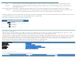
WDG:
If WDG is SET then the Watchdog Timer has Barked (timed out). Refer to Watchdog Control (+4C) for details on using the Watchdog Timer feature.

