7-72
Chapter 7
Programming Examples
Measurement Process Synchronization Examples
Example 4B: Generating Interrupts
It is also possible to generate interrupts using the status-reporting mechanism. The
status-byte bits can be enabled to generate a service request (SRQ) when set. In turn, the
instrument controller can be set up to generate an interrupt on the SRQ and respond to
the condition which caused the SRQ.
To generate an SRQ, a bit in the status byte is enabled using the command
SREn
. A one (1)
in a bit position enables that bit in the status byte. Hence,
SRE 8
enables an SRQ on bit 3,
the check-error queue, since the decimal value 8 equals 00001000 in binary
representation. Whenever an error is put into the error queue and bit 3 is set, the SRQ line
is asserted, illuminating the (S) indicator in the GPIB status block on the front panel of the
analyzer. The only way to clear the SRQ is to disable bit 3, re-enable bit 3, or read out all
the errors from the queue.
A bit in the event-status register can be enabled so that it is summarized by bit 5 of the
status byte. If any enabled bit in the event-status register is set, bit 5 of the status byte
will also be set. For example
ESE 66
enables bits 1 and 6 of the event-status register, since
in binary, the decimal number 66 equals 01000010. Hence, whenever active control is
requested or a front-panel key is pressed, bit 5 of the status byte will be set. Similarly,
ESNBn
enables bits in event-status register B so that they will be summarized by bit 2 in
the status byte.
To generate an SRQ from an event-status register, enable the desired event-status register
bit. Then enable the status byte to generate an SRQ. For instance,
ESE 32;SRE 32;
enables the syntax-error bit. When the syntax-error bit is set, the summary bit in the
status byte will be set. This will, in turn, enable an SRQ on bit 5 of the status byte, the
summary bit for the event-status register.
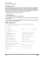
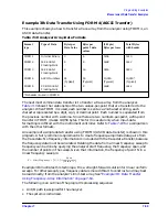
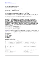
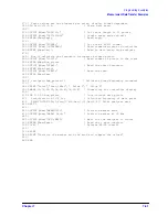
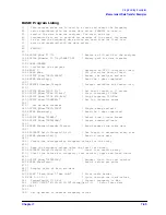
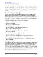
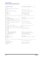
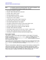
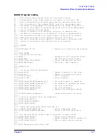
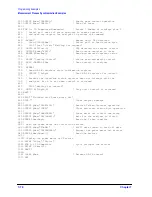
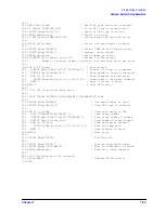
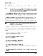
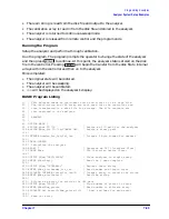
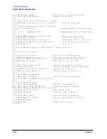
The following is an outline of the program's processing sequence:
• An I/O path is assigned for the analyzer.
• The system is initialized.
• The status registers are cleared.
• The event-status register bit 5 is enabled.
• The status-register bit 5 is enabled.
• The interrupt pointer is enabled and points to a subroutine.
• Two bad commands are sent to the analyzer to generate errors.
• The controller reads a serial-poll byte from GPIB in the event of an interrupt.
• The program tests for an SRQ.
• If the SRQ is not generated by the analyzer, the subroutine stops and displays
SRQ
FROM OTHER DEVICE
.
• If the SRQ was generated by the analyzer, the program reads the status byte and
event-status register.
• If bit 5 in the event-status register is set, the program prints:
SYNTAX ERROR FROM
ANALYZER
.
Summary of Contents for 8719ES
Page 15: ...1 1 1 Alphabetical Command Reference ...
Page 293: ...2 1 2 Introduction to Instrument Control ...
Page 310: ...3 1 3 GPIB Programming ...
Page 334: ...4 1 4 Reading Analyzer Data ...
Page 343: ...5 1 5 Data Processing Chain ...
Page 350: ...6 1 6 Error Reporting ...
Page 364: ...7 1 7 Programming Examples ...
Page 502: ...A 1 A Preset Conditions ...
Page 517: ...B 1 B Command Listings ...

