Building Firmware for the AT43DK370 Development Kit
AT43DK370 USB Host/Function Dev. Kit User Guide
5-7
3423C–USB–1/04
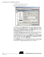
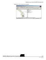
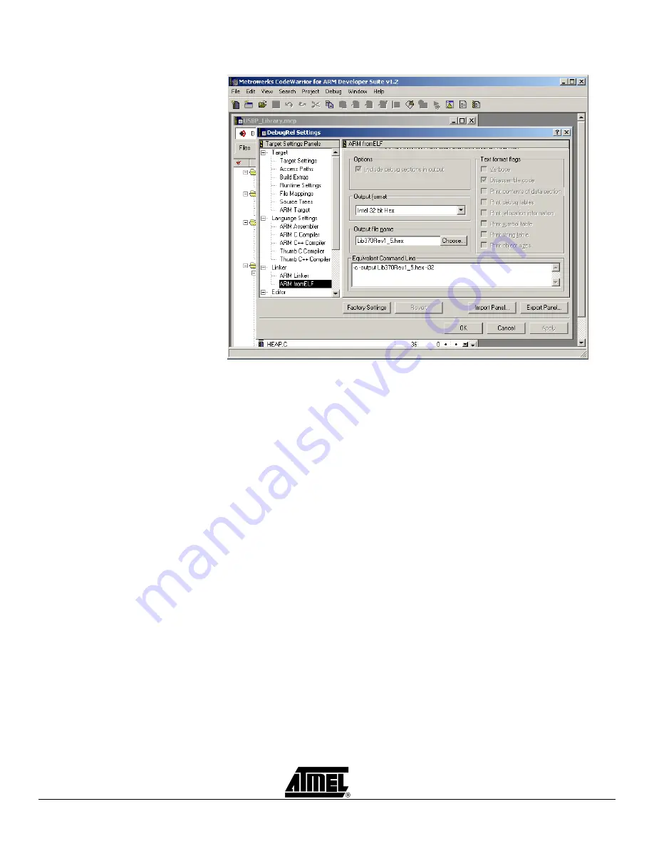
Figure 5-5.
Output Format/Name Selection
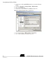
Secondly, for the ICE mode, the firmware entry point needs to be 0x1000. Go to Linker
> ARM Linker > Options and look for the Image entry point prompt. At the prompt
enter
0x1000
to set the proper entry point.
Thirdly, in addition to the Hex files, ADS can also create supporting files such as the
Image Map file and Symbol file during the Make process. The Image Map file maps
each section of the object file to the actual location in memory, and the Symbol file
maps each variable to the actual memory location. These two files provide the neces-
sary memory locations that the user can use, along with the Fill/Read Memory function
in the USB Clinic, to check the validity of software.
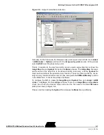
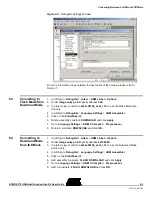
To configure the ADS to create the Image Map and Symbol files, go to Linker > ARM
Linker > Listings. On the Listings window, there is an Image Map and Symbols
check box. Check the desired file(s) and enter the file name at the List file name
prompt, as shown in Figure 5-6.
Please note that creating the Symbol file increases the Make time significantly.
Summary of Contents for AT43DK370
Page 1: ...AT43DK370 USB Host Function Development Kit User Guide for Revision 1 3...
Page 2: ......
Page 6: ...Table of Contents iv AT43DK370 USB Host Function Dev Kit User Guide 3423C USB 1 04...
Page 8: ...Introduction 1 2 AT43DK370 USB Host Function Dev Kit User Guide 3423C USB 1 04...
Page 46: ...Technical Support 8 2 AT43DK370 USB Host Function Dev Kit User Guide 3423C USB 1 04...
Page 56: ...Appendices 9 10 AT43DK370 USB Host Function Dev Kit User Guide 3423C USB 1 04...

