Access from the user program
KL2542
29
Version: 2.0.0
5.2
Control and status byte
Channel 1
Process data mode
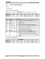
Control byte 1 (for process data mode)
Control byte 1 (CB1) is located in the
output image [
}
28]
, and is transmitted from the controller to the
terminal.
Bit
CB1.7
CB1.6
CB1.5
CB1.4
CB1.3
CB1.2
CB1.1
CB1.0
Name
RegAcces
s
Reset
Enable
GetLatchD
ata
enLatch
FallEdge
enLatch
RiseEdge
SetPos
disMixed
DecayMan
Key
Bit
Name
Description
CB1.7
RegAccess
0
bin
Register communication off (process data mode)
CB1.6
Reset
1
bin
all errors that may have occurred are reset by setting this bit
(rising edge)
CB1.5
Enable
1
bin
Enables channel 1
CB1.4
GetLatchData
0
bin
Show the current position in the input process data
1
bin
Show the current latch value in the input process data
CB1.3
enLatch FallEdge
1
bin
External latch event is enabled (for latch inputs with falling edge,
the terminal saves the current position)
CB1.2
enLatch RiseEdge
1
bin
External latch event is enabled (for latch inputs with rising edge,
the terminal saves the current position)
ATTENTION: Higher priority than CB1.3 !
CB1.1
SetPos
1
bin
Position value is set with register
R1 [
}
33]
(rising edge)
CB1.0
disMixed DecayMan
0
bin
Motor control via 2 pulsed transistors per half-wave
1
bin
Motor control via one pulsed and one switched transistor per
half-wave (manual deactivation. Automatic deactivation is
triggered through a threshold that is specified with register
R41
[
}
36]
).
Status byte 1 (for process data mode)
The status byte 1 (SB1) is located in the
input image [
}
28]
, and is transmitted from terminal to the controller.
Bit
SB1.7
SB1.6
SB1.5
SB1.4
SB1.3
SB1.2
SB1.1
SB1.0
Name
RegAccess Error
Warning
Ready
LatchData LatchValid SetPos
Ready
Input E1
Summary of Contents for KL2542
Page 2: ......

