REGISTERS
Copyright 2017
6-9
FibreXtreme Hardware Reference
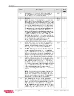
6.4.6 FPDP Flags (FPDP_FLGS)
– Offset 0x10
Field
Description
Access
Reset
Value
0
Send SYNC
– Write ‘1’ to send SYNC without DVALID.
Writing ‘0’ has no effect.
W
0
1
PIO1 Out
– State of the PIO1 line sent across the link.
R/W
0
2
PIO2 Out
– State of the PIO2 line sent across the link.
R/W
0
3
DIR Out
– State of the DIR line sent across the link.
R/W
0
4
NRDY Out
– State of the NRDY line sent across the
link.
R/W
0
7 to 5
Reserved.
None
0
8
SYNC Received
– A ‘1’ indicates a SYNC without
DVALID has been received. Cleared through ‘Clear
SYNC’ in the LINK_CTL register. A ‘0’ indicates no
SYNC has been received.
R
0
9
PIO1 In
– State of the PIO1 line received from the link.
R
0
10
PIO2 In - State of the PIO2 line received from the link.
R
0
11
DIR In
– State of the DIR line received from the link.
R
0
12
NRDY In
– State of the NRDY line received from the
link.
R
0
13
Rcvd STOP
– Indicates that a STOP flow control
primitive was received from the remote receiver. This
bit is read only and will be dynamically changing.
R
0
14
Sent STOP
– Indicates that a STOP flow control
primitive was sent to the remote transmitter. This bit is
read only and will be dynamically changing.
R
0
15
FIFO Overflow
– Indicates that the Remote Transmitter
FIFO Overflow bit was set in the received Status End of
Frame primitive (EOFa or EOFn Fibre Channel ordered
sets). This indicates that the remote node detected an
overflow condition in its transmit FIFO. This bit is read
only and will be dynamically changing.
R
0
16
Latched version of status bit 13. This bit is cleared by
writing a ‘0’ to it. It should be noted that this bit might
not appear to be cleared immediately after writing a ‘0’
to it. This is because another STOP may have been
received immediately after clearing it.
R/W
0
17
Latched version of status bit 14. This bit is cleared by
writing a ‘0’ to it. It should be noted that this bit might
not appear to be cleared immediately after writing a ‘0’
to it. This is because another STOP may have been
sent immediately after clearing it.
R/W
0
18
Latched version of status bit 15. This bit is cleared by
writing
a ‘0’ to it. It should be noted that this bit might
not appear to be cleared immediately after writing a ‘0’
to it. This is because another FIFO Overflow may have
been received immediately after clearing it.
R/W
0
31 to 19
Reserved.
None
0
Summary of Contents for FHF5-PC4MWB04-00
Page 2: ......
Page 8: ...Copyright 2017 iv FibreXtreme Hardware Reference ...
Page 26: ......
Page 40: ......
Page 48: ...SPECIFICATIONS Copyright 2017 5 8 FibreXtreme Hardware Reference ...
Page 50: ......
Page 68: ......
Page 74: ......
Page 76: ......
Page 78: ......
Page 84: ......
Page 86: ......
Page 96: ......


