QuickCam User's Manual
24
03-032-10187-04
DALSA
corp.
8:1
16:1
16:1
16:1
16:1
16:1
16:1
16:1
16:1
GPIO_OUT[0]
EXSYNC
PG_OUT[0]
IO
I1
I2
I3
I5
I4
I6
I7
GPIO_OUT[1]
GPIO_OUT[3]
PRIN
DIRECTION
CAM_CTRL[Not Used]
Q[17:0]
GPIO_TRIG
GPIO_LVAL
GPIO_FVAL
RSL_OUT
GP_CNT_EQ
GP_CNT_GT
GPIO_OUT[2]
GPIO_OUT[3]
CAM_CTRL[2]
CAM_CTRL[3]
DEL_OUT
GPIO_IN[0]
GPIO_IN[1]
GPIO_IN[2]
GPIO_IN[3]
CAM_IN[0]
CAM_IN[1]
CAM_IN[2]
CAM_IN[3]
GPIO_CTRL[0]
GPIO_CTRL[1]
GPIO_CTRL[2]
GPIO_CTRL[3]
Feed
b
ac
k
In
pu
ts
S+D
S
S
S
S
S+D
In
pu
t
S
ig
n
al
R
ou
ti
ng
Delayer
Rescaler
Mult 16 bit
input
backup
input
reference
8:1
4:1
PG_OUT[3:0]
Q[17,16,11,10,9,8,7,3]
PG_OUT[3:0];RSL_OUT
Q[0]
Q[1]
Q[2]
Q[3]
Q[4]
Q[5]
Q[6]
Q[7]
Q[12]
Q[13]
Q[14]
LUT
8-to-18
RSL_OUT
DEL_OUT
PG_OUT[1]
PG_OUT[2]
PG_OUT[3]
TS_TRIG[0]
Timestamp
Counter
Timestamp
Trigger
Generator
General
Purpose
Counter
up
clear
down
GP_CNT_EQ
GP_CNT_GT
TS_TRIG[3:0]
clear
set
Pulse_Gen0
Pulse_Gen1
Pulse_Gen2
Pulse_Gen3
Q[9]
Q[8]
Q[11]
Q[10]
PG_OUT[0]
PG_OUT[1]
PG_OUT[2]
PG_OUT[3]
trigger
5:1
8:1
8:1
8:1
Interrupt
FIFO
TIME[31:0]
Q[15]
TS_CNT[31:0]
GP_CNT[31:0]
GPIO_CNT[31:0]
LI[7:0]
GPIO_IRQ
MASK[7:0]
GP_CNT[31:0]
S+D
S+D
Q[17]
Q[16]
GPIO_OUT[2]
TS_TRIG[1]
TS_TRIG[2]
TS_TRIG[3]
Q[17,16,11,10,9,8,7,3]
interrupt
time
mask
Q[17,16,11,10,9,8,7,3]
Q[17,16,11,10,9,8,7,3]
Q[17,16,11,10,9,8,7,3]
TS_CNT[31:0]
trigger
trigger
trigger
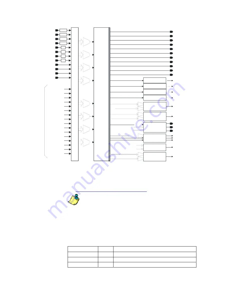
Note that all external inputs (from the camera, TTL inputs, and GPIO controls)
are resynchronized. The outputs from the look-up table are synchronous.
The LUT is programmed using a simple language. This language allows you to
create logical equations that specify the conditions that set particular outputs. See
also:
GPIO Control Block Programming Language
Note: There is a delay of two clock cycles between the inputs of the LUT
and its outputs. A clock cycle has a period of 30 nanoseconds, so the delay is 60
nanoseconds.
The signals in the GPIO Control Block are defined in the tables below.
Inputs to QuickCam are labeled I
n
(where n is an integer from 0 to 7) and
outputs are labeled Q
n
(where n is an integer from 0 to 15).
GPIO Input Labels
Input Signal
Label Description
GPIO_IN[0] * GPIO
0
input
GPIO_IN[1] GPIO
1
input
GPIO_IN[2] GPIO
2
input
Summary of Contents for QuickCam
Page 1: ...QuickCam User s Manual 30 Aug 06 03 032 10187 04 www dalsa com ...
Page 2: ......
Page 6: ...QuickCam User s Manual 4 03 032 10187 04 DALSA corp ...
Page 8: ...QuickCam User s Manual 6 03 032 10187 04 DALSA corp ...
Page 22: ...QuickCam User s Manual 20 03 032 10187 04 DALSA corp ...
Page 60: ...QuickCam User s Manual 58 03 032 10187 04 DALSA corp ...
Page 65: ...63 QuickCam User s Manul 03 032 10187 04 DALSA corp ...
Page 81: ...79 QuickCam User s Manul 03 032 10187 04 DALSA corp ...
Page 82: ...QuickCam User s Manual 80 03 032 10187 04 DALSA corp ...
Page 85: ...83 QuickCam User s Manul 03 032 10187 04 DALSA corp Z Zooming In or Out of an Image 16 ...


