Quick reference
28
(S
OFT
03.1
X
)
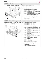
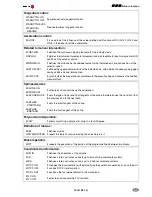
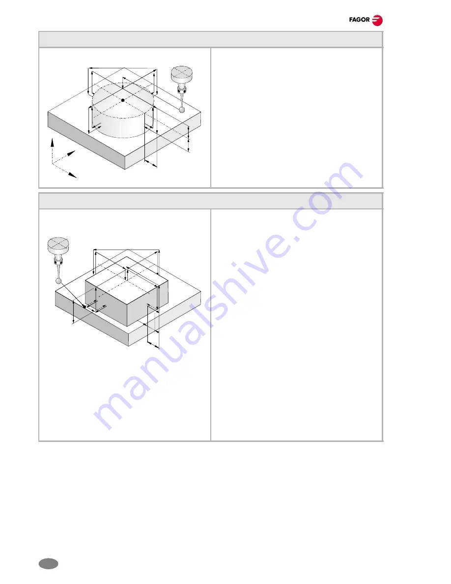
#PROBE 9. Circular boss measuring.
#PROBE 9 X Y Z B J E <C> H F
X..Z Coordinates of the boss center.
B
Safety distance.
J
Theoretical boss diameter.
E
Withdrawal distance after initial probing.
C
Point where the probing cycle ends.
• "C"=0: the probe returns to the point from where
the cycle was called.
• "C"=1: the cycle ends by positioning the probe
at the real center of the boss, at a "B"
distance from the programmed
coordinate.
H
Feedrate for the initial probing movement.
F
Probing feedrate.
#PROBE 10. Rectangular part centering
#PROBE 10 <X Y Z> I J <K> <L> <B> D E <H>
<F> <Q>
X..Z Probe position when calling the cycle.
I
Part length along the abscissa axis.
J
Part length along the ordinate axis.
K
Axis and direction of the first probing movement.:
• "K"=0: the probe moves in the positive direction
of the X axis.
• "K"=1: the probe moves in the negative direction
of the X axis.
• "K"=2: the probe moves in the positive direction
of the Y axis.
• "K"=3: the probe moves in the negative direction
of the Y axis.
L
Surface coordinate measuring:
• "L"=0: the cycle does not measure the surface
coordinate.
• "L"=1: the cycle measures the surface
coordinate.
B
Safety distance.
D
Safety distance along Z.
E
Withdrawal distance after initial probing.
H
Feedrate for the initial probing movement.
F
Probing feedrate.
Q
Feedrate for approach movements.
Z
X
Y
B
B
B
D
B
E
Summary of Contents for CNC 8070
Page 1: ...Quick reference SOFT 03 1X REF 0706 CNC 8070...
Page 44: ......

