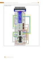
Chapter 17 74HC595 & LEDBar Graph
184
30
31
32
33
34
35
36
37
38
39
40
41
42
43
44
45
46
47
48
49
50
51
52
53
54
55
56
57
58
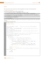
i f
(
wiringPiSetup
()
= =
-
1
) {
//when initialize wiring failed,print messageto screen
printf
(
"setup wiringPi failed !"
) ;
r e turn
1
;
}
pinMode
(
dataPin
,
OUTPUT
);
pinMode
(
latchPin
,
OUTPUT
);
pinMode
(
clockPin
,
OUTPUT
);
w h ile
(
1
){
x
=
0x01
;
f o r
(
i
=
0
;
i
<
8
;
i
++){
digitalWrite
(
latchPin
,
LOW
);
// Output low level to latchPin
_shiftOut
(
dataPin
,
clockPin
,
LSBFIRST
,
x
);
// Send serial data to 74HC595
digitalWrite
(
latchPin
,
HIGH
);
// Output high level to latchPin, and 74HC595
will update the data to the parallel output port.
x
< < =
1
;
// make the variable move one bit to left once, then the bright LED
move one step to the left once.
delay
(
100
);
}
x
=
0x80
;
f o r
(
i
=
0
;
i
<
8
;
i
++){
digitalWrite
(
latchPin
,
LOW
);
_shiftOut
(
dataPin
,
clockPin
,
LSBFIRST
,
x
);
digitalWrite
(
latchPin
,
HIGH
);
x
> > =
1
;
delay
(
100
);
}
}
r e turn
0
;
}
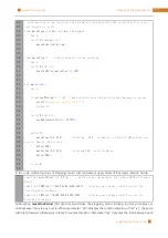
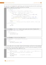
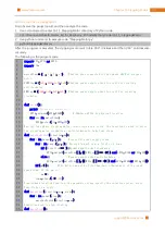
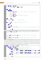
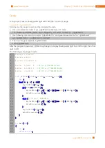
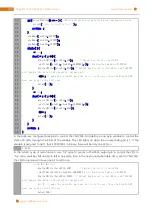
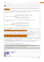
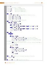
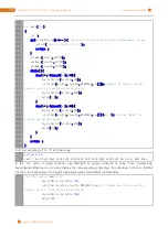
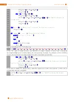
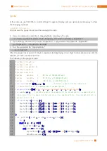
In the code, we configure three pins to control the 74HC595. And define a one-byte variable to control the
state of 8 LEDs through the 8 bits of the variable. The LED lights on when the corresponding bit is 1. If the
variable is assigned to 0x01, that is 00000001 in binary, there will be only one LED on.
x
=
0x01
;
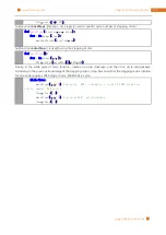
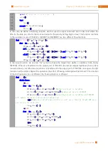
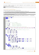
In the “while” cycle of main function, use “for” cycle to send x to 74HC595 output pin to control the LED. In
“for” cycle, x will be shift one bit to left in one cycle, then in the next round when data of x is sent to 74HC595,
the LED turned on will move one bit to left once.
for
(
i
=
0
;
i
<
8
;
i
++){
digitalWrite
(
latchPin
,
LOW
);
// Output low level to latchPin
_shiftOut
(
dataPin
,
clockPin
,
LSBFIRST
,
x
);// Send serial data to 74HC595
digitalWrite
(
latchPin
,
HIGH
);
// Output high level to latchPin, and 74HC595
will update the data to the parallel output port.
x
<<=
1
;
// make the variable move one bit to left once, then the bright LED
move one step to the left once.
delay
(
100
);
Summary of Contents for Ultimate Starter Kit
Page 1: ...Free your innovation Freenove is an open source electronics platform www freenove com ...
Page 117: ...117 Chapter 9 Potentiometer RGBLED www freenove com support freenove com Hardware connection ...
Page 155: ...155 Chapter 14 Relay Motor www freenove com support freenove com Hardware connection OFF 3 3V ...
Page 173: ...173 Chapter 16 Stepping Motor www freenove com support freenove com Hardware connection ...
Page 239: ...239 Chapter 22 Matrix Keypad www freenove com support freenove com Circuit Schematic diagram ...
Page 240: ...Chapter 22 Matrix Keypad 240 www freenove com support freenove com Hardware connection ...

