79
Chapter 4 Analog & PWM
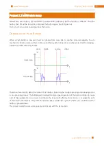
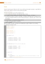
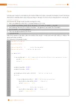
After the program is executed, you'll see that LED is turned from on to off and then from off to on gradually
like breathing.
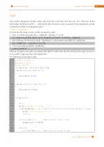
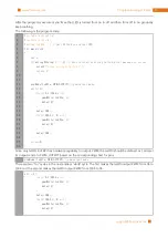
The following is the program code:
1
2
3
4
5
6
7
8
9
10
11
12
13
14
15
16
17
18
19
20
21
22
23
24
25
26
#include <wiringPi.h>
#include <stdio.h>
#define ledPin 1
//Only GPIO18 can output PWM
int
main
(
void
)
{
int
i
;
if
(
wiringPiSetup
()
==
-
1
){
//when initialize wiring failed,print message to screen
printf
(
"setup wiringPi failed !"
);
return
1
;
}
pinMode
(
ledPin
,
PWM_OUTPUT
);//pwm output mode
while
(
1
){
for
(
i
=
0
;
i
<
1024
;
i
++){
pwmWrite
(
ledPin
,
i
);
delay
(
2
);
}
delay
(
300
);
for
(
i
=
1023
;
i
>=
0
;
i
--){
pwmWrite
(
ledPin
,
i
);
delay
(
2
);
}
delay
(
300
);
}
return
0
;
}
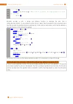
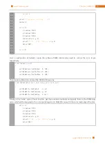
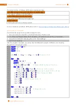
Since only GPIO18 of RPi has hardware capability to output PWM, the ledPin should be defined as 1 and set
its output mode to PWM_OUTPUT based on the corresponding chart for pins.
pinMode
(
ledPin
,
PWM_OUTPUT
);//pwm output mode
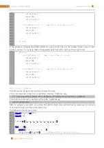
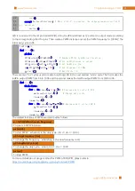
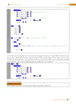
There are two “for” cycles in the next endless “while” cycle. The first makes the ledPin output PWM from 0% to
100% and the second makes the ledPin output PWM from 100% to 0%.
while
(
1
){
for
(
i
=
0
;
i
<
1024
;
i
++){
pwmWrite
(
ledPin
,
i
);
delay
(
2
);
}
delay
(
300
);
for
(
i
=
1023
;
i
>=
0
;
i
--){
pwmWrite
(
ledPin
,
i
);
delay
(
2
);
}
Summary of Contents for Ultimate Starter Kit
Page 1: ...Free your innovation Freenove is an open source electronics platform www freenove com ...
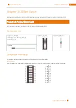
Page 117: ...117 Chapter 9 Potentiometer RGBLED www freenove com support freenove com Hardware connection ...
Page 155: ...155 Chapter 14 Relay Motor www freenove com support freenove com Hardware connection OFF 3 3V ...
Page 173: ...173 Chapter 16 Stepping Motor www freenove com support freenove com Hardware connection ...
Page 239: ...239 Chapter 22 Matrix Keypad www freenove com support freenove com Circuit Schematic diagram ...
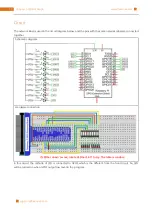
Page 240: ...Chapter 22 Matrix Keypad 240 www freenove com support freenove com Hardware connection ...

