background image

Glorious GZ5 Operation Manual/

17

g0 x—— y——

XY axis returns to the initial position of the tool path

If don`t change tool
If the B-axis needs to change angle

gosub azxy_safe

Return to A->Z->X->Y safe position.

g0 a—— b——

A-axis and B-axis return to the initial angle of the program.

s—— m3

Set the speed of the spindle,turn on spindle.

g0 x—— y——

XY axis returns to the initial position of the program.

If the B-axis does not change angle

If the A-axis need to change angle

gosub azxy_safe

Return to A->Z->X->Y safe position.

g0 a—— b——

A-axis and B-axis return to the initial angle of the tool path.

s—— m3

Set the speed of the spindle,turn on spindle.

g0 x—— y——

XY axis returns to the initial position of the program.

If the A-axis does not change angle

gosub z_safe

Z axis back to the highest position.

g0 a—— b——

A-axis and B-axis return to the initial angle of the tool path.

s—— m3

Set the speed of the spindle,turn on spindle.

g0 x—— y——

XY axis returns to the initial position of the program.

End Judgement

End Judgement

End Judgement

(End Tool Path )

gosub z_safe

Z axis back to the highest position.

g0 a0.0

A-axis return to angle 0

.

(End)

m9

Stop vacuuming.

m5

Stop spindle.

m100

Measure tool loss.

t0 m6

Spindle tool return.

g30

Back to the second reference point of the machine tool.

m101

Back to origin.

m30

End of program.

The positive direction of the X axis is the international standard direction

Summary of Contents for GZ5

Page 1: ...GZ5 Operation Manual 5 Axis Zirconia Dental Cutting Machine...

Page 2: ...Whiteth GZ5 Accessories List 6 3 2 Installation guide of GZ5 6 Equipment Operation Guidance 9 4 1 How To Use 9 4 2 Precautions 9 4 3 Solution After An Alarm Occurs 10 4 4 Material Saving Mode Fixture...

Page 3: ...ous types of dentures to fit the individual needs of customers 1 2 Equipment Features Feature one Comprehensive Alarm System This equipment has a comprehensive alarm system it can provide warning duri...

Page 4: ...a touchable operation panel and WIFI built in which can be remotely controlled and convenient for training diagnosis and maintain Each equipment has an independent ID When the equipment has a problem...

Page 5: ...tion which ensures the accuracy of the equipment and avoids errors when it begins to formal cut These can save time and materials Feature six Various Fixture Modes The equipment fixture can be adjuste...

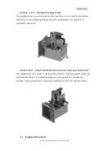
Page 6: ...ing causing dust to be unable to be completely sucked out Feature eight Long Term Maintenance Accuracy and Longer Service Life The equipment is a box structure each axis has 4 sliders with high rigidi...

Page 7: ...llation Environment 2 1 GZ5 s Installation Environment and Conditions As some parts of the equipment have certain requirements on the environment please confirm the following installation environment...

Page 8: ...Glorious GZ5 Operation Manual 6 machine to ensure the normal use of the machine Equipment Accessories and Installation 3 1 Whiteth GZ5 Accessories List 3 2 Installation guide of GZ5...

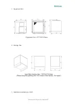
Page 9: ...Glorious GZ5 Operation Manual 7 1 Equipment Size 2 Package Size 3 Installation instructions of GZ5...

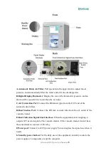
Page 10: ...ir pipe from the OUT end of the automatic drain filter D Dust Suction Port Connect the 31mm vacuum tube from the air outlet of the vacuum cleaner E Dust Collection Signal Line Interface When the equip...

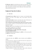
Page 11: ...ol panel and return to the origin 4 Place the tool Place the tool according to the number marked on the tool library No 1 R1 0 L18 No 2 R0 5 L16 No 3 R0 3 L10 5 Reconfirm that the tools are placed cor...

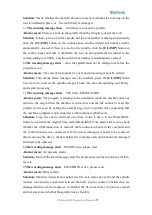
Page 12: ...d press RUN to continue working when it reaches 450 or more 2 The warning message show Error probe damage Alarm reason Signal error of the tool setting instrument or the tool setting instrument is dam...

Page 13: ...SIMULATION Alarm reason The program is running in the simulation mode the machine does not return to the origin when the machine is turned on and the file cannot be read the prompt can be seen by pul...

Page 14: ...rubber block No and the zirconia block with glue The plastic secondary clamp has a clamping position to ensure that the material is in a fixed position each time when it is clamped There is no need t...

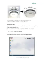
Page 15: ...ncluded in the Factory packing box Adjustment Method 1 Turn off the machine turn to the back of the fixture remove the secondary fixture screws and remove fixture No 2 Replace the fixture cover No and...

Page 16: ...calibrated processing file 3 Select the calibration block file Calibrate304 around or in the middle of Calibrate304 the difference between the two is limited to the different layout positions which ca...

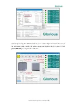
Page 17: ...on Manual 15 4 After processing the calibration block use a vernier caliper to measure the size of the calibration block modify the value column and confirm that it is correct Click CALIBRATE to compl...

Page 18: ...G code initialization Tool Path Begin if need to change tool m9 Stop vacuuming m5 Stop spindle gosub azxy_safe Return to A Z X safe position g0 b0 0 B axis return to angle 0 If there is no tool on the...

Page 19: ...Set the speed of the spindle turn on spindle g0 x y XY axis returns to the initial position of the program If the A axis does not change angle gosub z_safe Z axis back to the highest position g0 a b...

Page 20: ...ion of the Z axis international standard direction The positive direction of the A axis is the opposite of the international standard direction International standard direction of the positive directi...
Page 21: ...Glorious GZ5 Operation Manual 19...

Reviews: