Honeywell
Control Panel
39
8
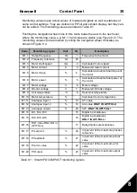
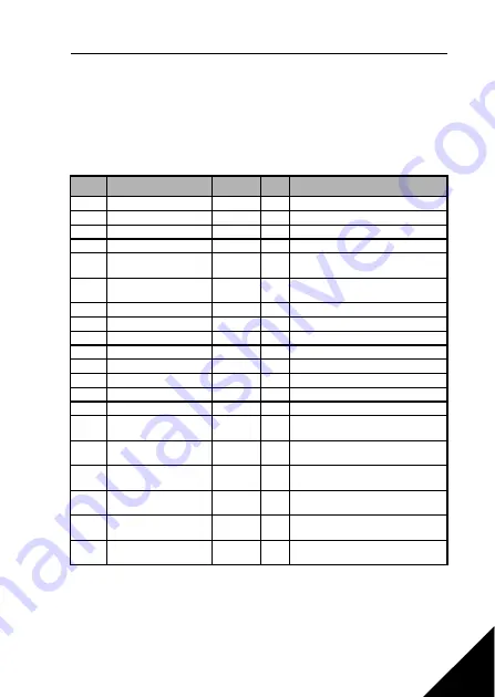
Monitoring values mean actual values of measured signals as well as statuses of
some control settings. They are visible in API Full and Limited display, but they can-
not be edited. The monitoring values are listed in Table 8.1.
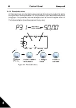
Pushing the navigation wheel once in this menu takes the user to the next level,
where the monitoring value, e.g. M1.11 and value are visible (see Figure 8.2). The
monitoring values can be browsed by rolling the navigation wheel clockwise, as
shown in Figure 8.4.
Code
Monitoring signal
Unit
ID
Description
M1.1
Output frequency
Hz
1
Frequency to the motor
M1.2
Frequency reference
Hz
25
M1.3
Motor shaft speed
rpm
2
Calculated motor speed
M1.4
Motor current
A
3
Measured motor current
M1.5
Motor torque
%
4
Calculated actual/nominal torque of
the motor
M1.6
Motor power
%
5
Calculated actual/nominal power of
the motor
M1.7
Motor voltage
V
6
Motor voltage
M1.8
DC-link voltage
V
7
Measured DC-link voltage
M1.9
Unit temperature
°C
8
Heat sink temperature
M1.10
Motor temperature
%
Calculated motor temperature
M1.11
Analogue input 1
%
13
AI1 value
M1.12
Analogue input 2
%
14
AI2 value
ONLY IN API FULL!
M1.13
Analogue output
%
26
AO1
ONLY IN API FULL!
M1.14
DI1, DI2, DI3
15
Digital input statuses
M1.15
DI4, DI5, DI6
16
Digital input statuses
ONLY IN API FULL!
M1.16
RO1, (also RO2, DO in
API FULL)
17
Relay/digital output statuses
M1.17
PI setpoint
%
20
In percent of the maximum process
reference
M1.18
PI feedback
%
21
In percent of the maximum actual
value
M1.19
PI error value
%
22
In percent of the maximum error
value
M1.20
PI Output
%
23
In percent of the maximum output
value
Table 8.1 : SmartVFD COMPACT monitoring signals

