


Regency
®
Model 4724 Control Expander Installation Manual (P/N 150596-02, Rev. A)
Revised 8/98
61
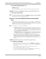
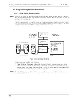
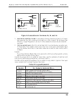
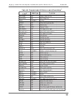
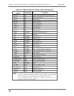
Shown below are three examples of programmable I/O statements that can be used on the 4724
to obtain customized status outputs.
Examples:
1.
The following statement will cause Terminal 15 on the 4720 to produce an active low out-
put whenever there is a fire alarm in any area.
TER15 = FIRE
2.
The following statement will cause Terminal 16 on the 4720 to produce an active low out-
put whenever there is an intrusion alarm In any area.
TER16 = INTRU
3.
The following statement will cause the X-10 Module Address 1 from the first house code
to be activated whenever Area 1 (or a non-area system) is in entry or exit delay. The mod-
ule could then be used to activate entry lighting. The unit will be deactivated when the
entry/exit delay ends or the area is disarmed.
X10[1].0 = (AEXIT[1] OR AENTRY[1])
Section 10: Walk Test Operation
The 4724 Walk Test mode allows you to test the system without causing Alarm Reports. Fol-
low the procedure below to perform a Walk Test:
1.
Press
2 TEST
followed by Code 0 or Code 1.
2.
The display will show either “WALK TEST” or your customized walk test message (see
Section 8.9 of this manual).
3.
Arm individual areas or the entire installation. Then violate the sensors by walking
through the armed areas. The system will operate as normal, except that it will not report
alarms to the central station and alarm tones will not be sent to the external bell. The alarm
conditions will be displayed on the touchpad LCD and annunciated on the internal speak-
ers. Interior zones can be armed or disarmed during the test to verify operation of the inte-
rior control key and options.
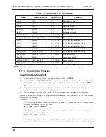
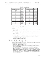
Table 21: Zone Groups
Bracketed Number
[N]
Zones
Bracketed Number
[N]
Zones
[1]
1-8
[10]
73-80
[2]
9-16
[11]
81-88
[3]
17-24
[12]
89-96
[4]
25-32
[13]
97-104
[5]
33-40
[14]
105-112
[6]
41-48
[15]
113-120
[7]
49-56
[16]
121-128
[8]
57-64
[17]
129-136
[9]
65-72
[18]
137-144


