background image


61 


customize the other values, if the use of digital port to receive the value of the sensor returns 

only "0" and "1", but to determine the same way. The reason why I did not use digital IO, because 

we use the digital IO port in other places. */


intval 

=


150

;


/*Set a PWM value, the maximum value of PWM is 255, but the speed should not 

be too fast when tracing the car, otherwise the car will shake more in the tracing process.*/


analogWrite 

(

M1

,


0

);


analogWrite

(

E1

,

 val

);


//the speed value of motorA is val 


analogWrite 

(

M2

,


0

);


analogWrite

(

E2

,

 val

);


//the speed value of motorB is val 


}


else


if

((

right1 

<=


8

)


&&


(

centre 

>=


975

)


&&


(

left1 

>=


975

))


{

/* The value collected to judge, 

if the center > = 975 and left1 > = 975 are greater than 975, indicating that the middle and left 

sensors did not detect the black line, right1 <= 8 shows the right sensor detects a black line, then 

the car Has left to the left, or the black line has been turning to the right, so the car should 

turn to the right. */


intval 

=


150

;


analogWrite 

(

E1

,


0

);


analogWrite

(

M1

,

 val

);


//the speed value of motorA is val 


analogWrite 

(

M2

,


0

);


analogWrite

(

E2

,

 val

);


//the speed value of motorB is val 


}


else


if

((

right1 

>=


975

)


&&


(

centre 

>=


975

)


&&


(

left1 

<=


8

))


{

/* Judge the collected value, if 

center > = 975 and right1 > = 975 are greater than 975, indicating that the middle and right sensors 

did not detect the black line, left1 <= 8 shows that the left sensor detects the black line, then 

the car Has been to the right deviation, or the black line has turned to the left, so the car should 

turn left at this time. */


intval 

=


130

;


analogWrite 

(

M1

,


0

);


analogWrite

(

E1

,

 val

);


//the speed value of motorA is val 


analogWrite 

(

E2

,


0

);


analogWrite

(

M2

,

 val

);


//the speed value of motorB is val 


}


if


((

right1 

<=


8

)


&&


(

centre 

<=


8

)


&&


(

left1 

<=


8

))


{

/* The value collected to judge, if the 

center <= 8, left1 <= 8 and right1 <= 8 are greater than 8, indicating 3 sensors have detected a 

black line, then the car has reached the "ten" intersection, because We have only 3 sensors, no way 

to make more sophisticated judgments, so only let the car choose to go straight. */


intval 

=


130

;


analogWrite 

(

M1

,


0

);


analogWrite

(

E1

,

 val

);


//the speed value of motorA is val 


analogWrite 

(

M2

,


0

);


analogWrite

(

E2

,

 val

);


//the speed value of motorB is val 


}


}


Summary of Contents for Hummer-Bot-1.0

Page 1: ...Hummer Bot 1 0 Instruction Manual V 2 0 ...

Page 2: ...Review Baron li 2018 3 11 V 1 5 Modifyir blutooth module Ken chen 2018 4 20 V 1 6 Add device instructions Baron li 2018 5 3 V 1 7 Add installation details picture Baron li 2018 6 26 V 1 8 1 Fix Servo lib conflict with pwm 2 Review and fix some error Luna ken 2019 1 2 V 1 9 1 Installation modification 2 Bom modification Carl 2019 1 9 V 2 0 Install and modify the acrylic sheets Carl ...

Page 3: ... wiring 21 3 1 5 Keywish Uno R3 board installation 23 3 1 6 Battery box installation 24 3 1 7 Servo installation 25 3 1 8 Infrared obstacle avoidance module installation 27 3 1 9 Voltage display module and DC head installation 28 3 1 10 Infrared remote control receiver installation 30 3 1 11 Overall assembly 31 3 1 12 Expansion board wiring diagram 32 3 2 Hummer Bot Module experiment 34 3 2 1 Walk...

Page 4: ...ion the library files used in the source codes are put into the corresponding path you only need to see corresponding phenomenon of the car and personally experience the process of experiment by downloading the source codes to Arduino via the serial port emulator This manual is very suitable for students and electronic enthusiasts to learn all course videos will be synchronized to https github com...

Page 5: ...3000mZh 3 7V rechargeable lithium battery with longer endurance Remaining capacity of battery real time detection Infrared remote control Bluetooth app control PS2 handle control optional Product Device List ...

Page 6: ...AC DC adapter or battery Technical specifications Working voltage 5V Input voltage USB powered or external 7V 12V DC input Output voltage 5V DC output and 3 3V DC output and external power input Microprocessor ATmega328 Chip data sheet is in the documentation Bootloader Arduino Uno Clock frequency 16 MHz Support USB interface protocol and power supply without external power supply Support ISP down...

Page 7: ...can see the interface as shown in Figure 2 1 1 In this interface we can see the different versions of the IDE and different operating environments Everyone can download according to their own computer system of course There will be a downloaded installation package on our companion CD but only the Windows version because this tutorial is all running under Windows system Figure 2 1 1 ArduinoIDE dow...

Page 8: ...My Computer Properties Device Manager Viewing Ports COM and LTP If you can see as the Figure 2 1 4 Figure 2 1 4 Driver installation success interface That indicates the driver has been installed successfully At this time we open the IDE select the corresponding development board model and port in the toolbar to use normally If you see Figure 2 1 5 it means that the computer does not recognize the ...

Page 9: ...ct Device Manager find the viewing ports COM and LPT If there is a yellow Arduino UNO exclamation point this means you need to install the driver yourself 3 If you install the driver again and again it eventually fails Please uninstall the driver and re install install the driver automatically restart the computer 2 1 2 Install Driver 1 If your computer is a Windows 7 system 1 Right click on My Co...

Page 10: ...7 Figure 2 1 6 Updated Driver Interface 2 Next select the Browse my computer for driver software option Figure 2 1 7 Driver Update Selection Screen ...

Page 11: ...d FTDI USB Drivers located in the Drivers folder of the Arduino software download Figure 2 1 8 Driver file selection interface 4 If you have already installed the following figure will automatically inform you that the driver was successful ...

Page 12: ... time we return to the Device Manager interface the computer has successfully identified Arduino as shown in the below Figure 2 1 10 then open the Arduino compilation environment you can open the Arduino trip Figure 2 1 10 Driver Success Recognition Interface Note ...

Page 13: ... 4 The system will reboot to the Select an option screen 5 Select Troubleshooting from the Select an option screen 6 Select Advanced Options from the Troubleshoot screen 7 Select Windows startup settings screen from Advanced Options 8 Click the Restart button 9 The system will reboot to the Advanced Boot Options screen 10 Select Disable Driver Signature Enforcement 11 Once the system is booted you...

Page 14: ...nners The Preference option It s mainly about the parameter settings such as language fonts and so on Figure 2 1 13 File Menu Bar Options 3 Click Tools the interface shown in Figure 2 1 14 will pop up Here we can see two options Board and Port In the board option we can see the commonly used Arduino development board model we only need to choose according to their own development board In the Port...

Page 15: ...ove steps the Arduino IDE will work You can open any program in Examples First compile the program If it is compiled correctly it can be directly downloaded to the development board and the corresponding device of the connection number With wires you can see the corresponding phenomenon ...

Page 16: ...nt Figure 3 1 1 Schematic diagram of motor mounting Note You need to use the screw to pass through the front hole of the motor the motor holder corresponds to the opposite position and use the nut to fix the motor holder Figure 3 1 2 Effect diagram of motor mounting Step2 You need to solder the wire to the motor ...

Page 17: ...14 Figure 3 1 3 Effect diagram of solder the wire Step3 You need to fix the wire with a cable tie Figure 3 1 4 Effect diagram of fixing the wire ...

Page 18: ...15 Step4 You need to install motors Figure 3 1 5 Schematic diagram of motor installation ...

Page 19: ... motor installation 3 1 2 Wheel and drive module installation Step1 You need to install hexagonal coupling Figure 3 1 7 Schematic diagram of hexagonal coupling installation Figure 3 1 8 Effect diagram of hexagonal coupling installation ...

Page 20: ...ll wheel Figure 3 1 9 Schematic diagram of wheel installation Note The black top wire position of the hexagonal coupling is tightened against the plane of the motor drive shaft Figure 3 1 10 Effect diagram of wheel installation ...

Page 21: ...18 Step3 You need to install motor driver module Figure 3 1 11 Shematic diagram of fixing motor driver board Figure 3 1 12 Shematic diagram of fixing motor driver board ...

Page 22: ...19 3 1 3 Tracking module installation Figure 3 1 15 Shematic diagram of copper column of tracking moduble installation Figure 3 1 16 Effect diagram of copper column of tracking moduble installation ...

Page 23: ... 17 Shematic diagram of tracking moduble installation Note You need to screw the M3 nut to the bottom of the M3 10 screw and install it Figure 3 1 18 Effect diagram of copper column of tracking moduble installation ...

Page 24: ...c plate copper column installation and motor wiring Figure 3 1 19 Shematic diagram of motor wiring Note You need to insert the 4Pin DuPont cable into the motor drive board input Figure 3 1 20 Effect diagram of motor wiring ...

Page 25: ...22 Figure 3 1 21 Shematic diagram of copper column installstion Figure 3 1 22 Effect diagram of copper column installstion ...

Page 26: ...23 3 1 5 Keywish Uno R3 board installation Figure 3 1 23 Shematic diagram of Keywish Uno R3 board installation Figure 3 1 24 Effect diagram of Keywish Uno R3 board installation ...

Page 27: ...24 3 1 6 Battery box installation Figure 3 1 25 Shematic diagram of battery box installation Figure 3 1 26 Effect diagram of battery box installation ...

Page 28: ...of the servo we need to adjust the servo to 90 degrees First we should copy the following program Lesson ModuleDemo Servo ServoCorrect ServoCorrect ino into the compilation environment Then we need to make the signal line of servo orange be connected to port 13 of Arduino board Finally we need to fix rudder wing by screws and fix the ultrasonic bracket on the rudder wing ...

Page 29: ...h 13 attaches the servo on pin 13 to the servo object void loop myservo write pos tell servo to go to position in variable pos delay 15 waits 15ms for the servo to reach the position Figure 3 1 29 Schematic diagram of rudder wing and ultrasonic bracket installation Figure 3 1 30 Effect diagram of rudder wing and ultrasonic bracket installation ...

Page 30: ...27 3 1 8 Infrared obstacle avoidance module installation Figure 3 1 31 Shematic diagram of infrared obstacle module installation Figure 3 1 32 Effect diagram of infrared obstacle module installation ...

Page 31: ...er cables the same as the wires used by the motor one red and one black and connect the two wires to the DC power supply head DC power supply head as shown in Figure 3 1 34 You need to remove the rubber ring at the 1 mark to open the caser and solder the wire to 12V and GND as shown in Figure 3 19 3 Figure 3 1 34 Shematic diagram of solder DC power supply head ...

Page 32: ...29 Figure 3 1 35 Effect diagram of solder DC power supply head Figure 3 1 36 Effect diagram of voltage display module and DC head installation ...

Page 33: ... 10 Infrared remote control receiver installation Figure 3 1 37 Shematic diagram of infrared remote control receiver installation Figure 3 1 38 Effect diagram of infrared remote control receiver installation ...

Page 34: ...s shown in Figure 3 1 11 2 and connect the positive red wire to the 12V negative black wire to GND Figure 3 1 39 Shematic diagram of Overall assembly Note you need to take the infrared tracking wire and the driver board wire from the upper acrylic plate hole 1 plug the expansion board into the UNO R3 board and wire it ...

Page 35: ...32 Figure 3 1 40 Effect diagram of Overall assembly 3 1 12 Expansion board wiring diagram Figure 3 1 41 Expansion Board Connection Diagram The full installation of the car is as shown below ...

Page 36: ...ram So far the basic assembly of car has been completed Then you can achieve the corresponding functions only by downloading the program to the development board each function has a corresponding program in CD Let s go to the software section ...

Page 37: ...ignals allows or prohibits the device to work when the input signal is not interfered it has a logic power input terminal which can enable the internal logic circuit to work under low voltage and feedback the variation to the control circuit Especially the input can be connected directly with the MCU and easily controlled When the DC motor is driven the stepper motor can be directly controlled and...

Page 38: ...ing of two motors separately Controlling the stepper motor The speed control with PWM pulse width Positive and negative rotation Figure 3 2 2 Logic Function Chart Fig 3 2 3 Module Physical Map Detailed L298N chip data please refer to hummer bot Document L298N_datasheet pdf ENA IN1 IN2 Motor status H H L Forward H L H Reversal H IN2 IN1 Quick stop L X X Stop ...

Page 39: ...mulate the simulation output via square waves with different duty cycles Arduino PWM port outputs a series of square waves with fixed frequency the power and current of the motor can be amplified after receiving the signal thereby changing the motor s speed The speed coordination of two motors on the right and left wheels can achieve the forward backward turning and other functions of the car Figu...

Page 40: ...pply is added to the load the power supply is on otherwise the power supply is off As long as the bandwidth is enough any analog value can use PWM to encode The output voltage value is calculated by the on and off time Output voltage turn on time pulse time maximum voltage Fig 2 4 6 shows the corresponding voltage to the pulse change Figure 2 4 6 Relation between Pulse and Voltage Arduino UNO poss...

Page 41: ...e need to do a simple test to check if the motor can run normally So we need to copy the following code You can also open the program in the CD directly into the IDE development environment and downloading to the development board And turning on the power power connection is introduced the tenth and eleventh steps in 3 1 2 to observe the wheels rotation if going forward 5s stopping 1s going back 5...

Page 42: ...es of the motor may be reversed then you need to adjust slightly Program flow chart is as follows Figure 3 2 9 Motor Test Flow Chart Note This test and IO selection are only for reference you can choose other IO ports or use other wiring methods according to your own ideas ...

Page 43: ...rite M1 0 analogWrite E1 150 the speed value of motorA is 150 analogWrite M2 0 analogWrite E2 150 the speed value of motorB is 150 delay 5000 forward analogWrite M1 0 analogWrite E1 0 the speed value of motorA is 0 analogWrite M2 0 analogWrite E2 0 the speed value of motorB is 0 delay 1000 ...

Page 44: ...very strong the measurement accuracy is very high when the distance is moderate In addition the module can be assembled easily and used stop analogWrite M1 150 the speed value of motorA is 150 analogWrite E1 0 analogWrite M2 150 the speed value of motorA is 150 analogWrite E2 0 delay 5000 back analogWrite M1 0 analogWrite E1 0 the speed value of motorA is 0 analogWrite M2 0 analogWrite E2 0 the sp...

Page 45: ...screws in the kit Pin wiring definition only for reference you can define according to your own ideas arduino Uno Infrared Obstacle Avoidance Module VCC VCC GND GND A3 The left module A4 The right module Chart 3 2 1 Pin Wiring Definition 3 2 2 3 Module Parameters The working principle of infrared obstacle avoidance sensor is very simple that is the reflection property of objects In a certain range...

Page 46: ...st the detection distance by the potentiometer the detection distance is 2 30cm if it is found that the distance detection is not very sensitive you can use the potentiometer to achieve the desired results rotating the potentiometer clockwise will increase the detection distance counterclockwise will decrease it is shown in Fig 3 2 12 ...

Page 47: ...e figure shown below the upper column is the GND interface the middle column is the VCC interface and the lower column is the OUT interface where A3 corresponds to the OUT of the left infrared obstacle avoidance and A4 corresponds to the OUT of right infrared obstacle avoidance Figure 3 2 13 Wire connection diagram Adjustable Potentiometer ...

Page 48: ...iler environment you can also open the program directly in the CD downloading it to the development board opening the serial port monitor baud rate is 9600 and observing the changes of data when there is an obstacle Figure 3 2 14 and no obstacle Figure 3 2 15 Note Here we connect the infrared obstacle avoidance signal output port to the analog port on Arduino A0 A5 so the serial port prints out an...

Page 49: ...in A3 const int rightPin A4 int dl int dr void setup Serial begin 9600 pinMode leftPin INPUT pinMode rightPin INPUT delay 1000 void loop dl analogRead leftPin dr analogRead rightPin Serial print left Serial print dl Serial print Serial print right Serial println dr ...

Page 50: ...47 Figure 3 2 15 Diagram of Data without Obstacles ...

Page 51: ...m code Next we combined the above infrared obstacle avoidance module test program and the trolley motor driver program to complete the infrared obstacle avoidance experiment The program of this experiment hummer bot Lesson ModuleDemo InfraredAvoidance InfraredAvoidance ino ...

Page 52: ...gram in is executed dl 38 there is no obstacle on the left dr 38 shows that there is an obstacle on the right so at this time the car is turning to the side without obstacles ie turning to the left From Figure 3 2 11 we know that the simulated value will drop below about 35 in the event of an obstacle But in order to reduce the error we set the threshold at 38 to prevent the car from judging the e...

Page 53: ...n or equal to 38 the following program in is executed dl 38 indicating that there is an obstacle on the left and dr 38 shows that there is an obstacle on the right so at this time the car is rotated 180 degrees backwards In the experiment the car can just turn around 180 degrees after 500ms of rotation Because the DC motor can not precisely control the angle like the steering gear An approximate v...

Page 54: ...otation if you do not stop there will be the phenomenon of rotating around delay 1000 Turning right if dl 38 dr 38 Judge two values collected by the sensor If the value collected by the left sensor is greater than or equal to 38 and the right value is greater than or equal to 38 execute the following program in dl 38 indicating that there is no obstacle on the left and dr 38 that there is no obsta...

Page 55: ...ransistor The physical map is shown in Fig 3 2 16 Figure 3 2 16 Physical Map of the Module 3 2 3 2 Working Principle In the above we talked about two patterns of tracing the white line and the black line In fact either the black line or the white line we usually adopt the infrared detection method Infrared detection method means that different objects with different colors have the different infra...

Page 56: ...n the car is moving forward the driving track is always between the two first level sensors X1 and Y1 the black track as shown in Fig 3 2 18 when the car deviates from the black line If the left X1 detects the black line which can t be detected by the right Y1 and intermediate sensors the the car has shifted to the right then the car will turn left slightly and keeping intermediate sensor always d...

Page 57: ...e VCC to 3 3V or 5V the OUT output port to the microcontroller IO port directly The I O port on Arduino should be set for input mode receiving mode otherwise it can t be used As for other MCU such as ARM or more advanced control boards if the I O ports need to be used as the input and output mode they have to be set to the input mode receiving mode The 51 series microcontrollers can be used direct...

Page 58: ...on your own desires the best width of the tape is 13 18mm In this manual we use the black track as shown in Fig 3 2 20 3 Module test We should copy the following codes to the IDE compiler environment you can also open the program in the CD directly and downloading to the development board and open the serial port monitor baud rate is 9600 to observe the changes of data when there is the white line...

Page 59: ...nce to the analog port on Arduino A0 A5 so the serial port monitor prints analog values you can connect it to the digital port 2 13 then the serial port monitor will print out only 0 and 1 Demo test code hummer bot Lesson ModuleDemo InfraredTracingTest InfraredTracingTest ino ...

Page 60: ...al begin 9600 void loop int left centre right left analogRead A0 centre analogRead A1 right analogRead A2 Serial print right Serial print right Serial print Serial print centre Serial print centre Serial print Serial print left Serial print left Serial println ...

Page 61: ...ts the Black Line From Fig 3 2 21 and Fig 3 2 22 we can see that the output is high level when the sensor does not detect the black line low level when detects the black line We use the analog port to collect the sensor s signal so the printed value is analog that the high level is reaching 1024 the low level is 0 ...

Page 62: ...ll be implemented If the left sensor detects the black line the car should turn the left If the right sensor detects the black line the car should turn the right After the direction adjustment the car walks forward and continues to detect the black line repeatedly The tracing flow chart is shown in Fig 3 2 23 Figure 3 2 23 the Tracing Flow Chart 3 2 3 5 2 Program Code Code Path hummer bot Lesson M...

Page 63: ...id loop int left1 centre right1 Define 3 sensors left1 analogRead A0 centre analogRead A1 right1 analogRead A2 Read the value collected by 3 sensors if right1 975 centre 8 left1 975 Judge the collected value if right1 the sensor captures a value that is low and reads 0 after analog IO However to reduce the error we set the threshold In 8 to prevent the error caused by the car to determine the wron...

Page 64: ...gWrite E1 0 analogWrite M1 val the speed value of motorA is val analogWrite M2 0 analogWrite E2 val the speed value of motorB is val else if right1 975 centre 975 left1 8 Judge the collected value if center 975 and right1 975 are greater than 975 indicating that the middle and right sensors did not detect the black line left1 8 shows that the left sensor detects the black line then the car Has bee...

Page 65: ...ll rotate 90 degrees to the right After that the MCU reads data from the reflected ultrasonic again the steering engine rotates 180 degrees to the left then reading data again the steering engine rotate 90 degrees the MCU will contrast the two detected data if the left data is greater than the right data the car will turn left otherwise turn right if the two data are both less than the safety valu...

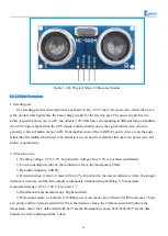
Page 66: ...histle At present most of the ultrasonic sensors are working using piezoelectric sensors Distance measurement with the ultrasonic is also a hot spot In the Hummer Bot car we use HC SR04 ultrasonic module which has the 2cm 400cm non contact distance sensing function the measurement accuracy can achieve to 3mm the temperature sensor can correct the measured results using the GPIO communication mode ...

Page 67: ...mber that the red is power wire the brown is ground wire 2 Ultrasonic wave 1 Working voltage 4 5V 5 5V In particular voltage above 5 5V is not allowed definitely 2 Power consumption current the minimum is 1mA the maximum is 20mA 3 Resonant frequency 40KHz 4 Detection range 4 mm to 4 meters Error 4 In particular the nearest distance is 4mm the longest distance is 4 meters and the data outputs conti...

Page 68: ... stop rotating When the control circuit receives the control signal the motor will rotate and drive a series of gear sets the signal will move to the output steering wheel when the motor decelerates The the output shaft of steering gear is connected with the position feedback potentiometer the potentiometer will output a voltage signal to the control circuit board to feedback when the steering gea...

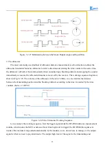
Page 69: ...ce diagram is shown in Fig 3 2 28 The velocity of the ultrasonic in the air is 340m s we can calculate the distance between the transmitting position and the blocking obstacle according to the time t recorded by the time counters that is s 340 t 2 Figure 3 2 28 the Ultrasonic Working Sequence Let us analyze the working sequence first the trigger signal starts the HC RS04 distance measurement modul...

Page 70: ...his will enhance the ultrasonic emission intensity The output end adopts two parallel inverters in order to improve the driving ability the resistance R1 and R2 on the one hand can improve the drive ability of the 74LS04 outputting high level on the other hand it can increase the damping effect of the ultrasonic transducer and shorten the free oscillation time The receiving circuit is composed of ...

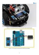
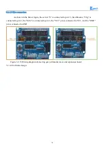
Page 71: ... Installing the steering gear ultrasonic module to the car which has been completed in fourth step to the seventh step in 3 1 2 as shown in Fig 3 2 31 2 Connecting the steering gear and ultrasonic module to the Arduino motherboard as shown in Fig 3 2 32 you can choose other IO ports according to your own ideas ...

Page 72: ...69 Figure 3 2 31 Installation Diagram of the Steering Gear and Ultrasonic Module Figure 3 2 32 Wiring of the Steering Gear and Ultrasonic Module ...

Page 73: ... is connected to pin 13 the ultrasonic Trlg is connected to pin 2 the Echo is connected to pin 3 the VCC pin is connected to VCC and the GND pin is connected to GND Figure 3 2 33 Wiring diagram of steering gear ultrasonic wave and expansion board 3 2 4 6 Software design ...

Page 74: ...71 3 2 4 6 1 Program flow chart 3 2 4 6 2 Program Code Code path hummer bot Lesson ModuleDemo UltrasonicAvoidance UltrasonicAvoidance ...

Page 75: ...llected by the ultrasonic module da is the value collected by the ultrasonic 90 degrees servo dl is the steering servo 180 degrees ultrasonic acquisition To the value at this point the steering gear has turned to the left of the car da for the servo 0 degrees ultrasonic collected value then the steering gear has turned to the right side of the car float left float right void setup Serial begin 960...

Page 76: ...lue of motorB is val Serial print Distance Serial print da Serial print Serial println Moving advance 50 delay 500 If the distance is more than 50cm move forward and output Moving advance 50 indicating that the obstacle is more than 50cm from the car if da 40 da 30 left 38 right 38 Judge the collected value da 50 da 30 meaning that when the distance between the frontal obstacle and the car is grea...

Page 77: ... execute the following program in the distance between the car and the obstacle has exceeded the safety value So the car stopped forward int val 0 digitalWrite M1 0 analogWrite E1 val the speed value of motorA is 0 digitalWrite M2 0 analogWrite E2 val the speed value of motorB is 0 Serial print Distance Serial print da Serial print Serial println Stopped If the distance is less than 20cm the car w...

Page 78: ...nitor head write 80 head steering back that is when the initialization 80 degrees position if dl 20 dl 1000 dl dr digitalWrite M1 0 analogWrite E1 180 the speed value of motorA is 180 digitalWrite M2 180 the speed value of motorB is 180 analogWrite E2 0 Serial println Turning left1 delay 200 determine the left and right distance if the left is larger than the left else if dl 1000 digitalWrite M1 1...

Page 79: ...ed receiver module the remote controller has 17 function keys the transmission distance is up to 8 meters which is very suitable for controlling equipment indoor The infrared receiving module can receive 38KHz modulation remote control signal Through the Arduino programming the decoding operation of Infrared wireless remote control signal can be realized so as to produce all kinds of remote contro...

Page 80: ...frared receiver photoelectric converter usually a photodiode or photoelectric triode here we use PIN photodiode converts the received infrared light instruction signal into a corresponding electrical signal The received signal is very weak and interference is particularly large in order to achieve the accurate detection and signal conversion in addition to the infrared photoelectric conversion dev...

Page 81: ...cuit Diagram and Physical Map of Infrared Receiving Head 3 2 5 2 Working Principle The remote control system in general composed of the remote controller transmitter and receiver when you press any button on the remote control it will generate the corresponding encoding pulse and output various control pulse signals based on the infrared infrared monitor diode sends the signal to the the amplifier...

Page 82: ...g to your own ideas Note Do not reverse power line otherwise the receiving head will burn up Figure 3 1 37 Infrared Module Connection Diagram 3 Copying the following program to IDE you can also directly open the matching program in the CD and downloading to the development board pulled out the transparent plastic sheet marked as 1 in the Fig 3 2 33 Then opening the serial port monitor observing an...

Page 83: ...80 Test code Path hummer bot Lesson ModuleDemo IrkeyPressed IrkeyPressed ino ...

Page 84: ... and 1 is the name of the key function of the remote controller include IRremote h IRremote ir 12 unsigned char keycode char str 128 void setup Serial begin 9600 ir begin void loop if keycode ir getCode String key_name ir getKeyMap keycode sprintf str Get ir code 0x x key name s n keycode char key_name c_str Serial println str else Serial println no key delay 110 ...

Page 85: ...ow figure the infrared receiver s s pin is connected to 12 pin the pin is connected to GND and the middle pin is connected to VCC ST_KEY_MAP irkeymap KEY_MAX 1 0x45 2 0x46 3 0x47 4 0x44 5 0x40 6 0x43 7 0x07 8 0x15 9 0x09 0 0x19 0x16 0x0D up 0x18 down 0x52 ok 0x1C left 0x08 right 0x5A ...

Page 86: ...83 3 2 5 5 Software Design 3 2 5 5 1 Program flow chart 3 2 5 5 2 Program code Code Path hummer bot Lesson ModuleDemo IRremote IRremote ino ...

Page 87: ...ies folder otherwise the program can not compile int E1 5 PWMA int M1 9 DIRA left int E2 6 PWMB int M2 10 DIRB right int RECV_PIN 12 long expedite1 0xFF6897 Define a long integer expedite1 variable and assign this variable 0xFF689 FF689 is the infrared remote control button encoding long expedite2 0xFFB04F long advance 0xFF18E7 long back 0xFF4AB5 long stop 0xFF38C7 long left 0xFF10EF long right 0x...

Page 88: ...ite1 execute the command in below here is the acceleration 1 command int val 200 analogWrite M1 0 analogWrite E1 val the speed value of motorA is val analogWrite M2 0 analogWrite E2 val the speed value of motorB is val delay 500 irrecv resume if results value expedite2 Judgment on the received value if the value is expedite2 execute the command below here for the acceleration 2 command int val 255...

Page 89: ... motorB is val delay 500 Rotate 500ms to the left and stop otherwise the car will always be spinning around analogWrite M1 0 analogWrite E1 0 the speed value of motorA is 0 analogWrite M2 0 analogWrite E2 0 the speed value of motorB is 0 analogWrite A1 180 irrecv resume if results value right Judgment on the received value if the value is right execute the command in the following here is the comm...

Page 90: ...te A2 180 irrecv resume if results value back Judgment on the received value if the value is back execute the command below here for the back instruction int val 150 analogWrite E1 0 analogWrite M1 val the speed value of motorA is val analogWrite E2 0 analogWrite M2 val the speed value of motorA is val delay 500 irrecv resume 接收下一个值 Serial println results value HEX Output the receive code in hexad...

Page 91: ... English manual pdf The physical diagram of module is shown in Fig 3 2 40 Fig 3 2 40 JDY 16 Module JDY 16 function introduction BLE high speed transparent transmission supports 8K Bytes rate communication Send and receive data without byte limit support 115200 baud rate continuously send and receive data Support 3 modes of work see the description of AT STARTEN instruction function Support serial ...

Page 92: ...ugh the serial port then Arduino to analyze the data packets and execute the corresponding actions The data format sent by the upper computer end Android is as follows which mainly contains 8 fields we use a structure to represent it Protocol Header Data Length Device Type Device Address Function Code Control Data Check Sum Protocol End Code In the 8 fields above we use a structural body to repres...

Page 93: ...n Data Length 7 bytes 01 is device type 01 is device address 06 is the transmission data such as motor LED buzzer and so on The 06 here refers to the transmission speed and the 05 refers to the transmission direction 50 or 0050 is the controlling data 0x50 in hexadecimal is 80 when converted to binary which means the speed value is 80 005F is the check sum that is 0x01 0x01 0x06 0x50 0x5F 55 is th...

Page 94: ...r and sliding it allows the car to rotate The I section is a data return area such as the current state speed of the car etc The H section is the data packet for example the data is AA 01 01 06 23 00 2B 55 At this time the speed is 35 23 is 16 hexadecimal data which means 35 when converted to 10 hexadecimal If the transmitted data is AA 08 01 01 05 00 5B 00 79 55 it means that the car is moving fo...

Page 95: ...ed board TXD port is connected to RXD port on the board as shown in Fig 3 2 52 Note Since Arduino UNO has only one serial port the Bluetooth must be disconnected from the serial port when downloading the program otherwise the download will fail Figure 3 2 51 Wiring Positions of Bluetooth ...

Page 96: ...re installation package on the CD latter we will launch the IOS version You will see that the flashing of the Bluetooth module indicator slows down after successful connection If you have downloaded the program to the development board before you can use the phone to control the car directly as shown in Fig 3 2 53 ...

Page 97: ...en dot marked as 1 in any direction the car will move towards the corresponding direction Switching on the gravity sensor marked in 2 the APP is switched to the gravity induction mode and you can control the movement direction of the car by shaking the mobile phone 3 2 6 5 Wire connection Bluetooth wire connection location as shown below ...

Page 98: ...95 3 2 6 6 Software Design 3 2 6 6 1 Program flow chart 3 2 6 6 2 Program Code Code Path hummer bot Lesson Advanced Experiment Buletooth Buletooth ino ...

Page 99: ...cv hummerbot hbot E1 M1 E2 M2 13 A0 void setup Serial begin 9600 hbot init void read_data void unsigned char avilable byte p readbuff memset p 0 32 readlen 0 while Serial available 0 if avilable Serial peek START_CODE avilable 1 if avilable if p Serial read END_CODE avilable 0 readlen Serial print p HEX break Serial print p HEX p readlen Serial print n void loop read_data ...

Page 100: ...recv switch recv function case E_BATTERY break case E_LED break case E_INFO break case E_ROBOT_CONTROL hbot drive protocol_prase_degree recv break case E_ROBOT_CONTROL_SPEED hbot setSpeed protocol_prase_speed recv break case E_VERSION break ...

Page 101: ...ceiver the handle uses two AAA batteries as power supply The controller and receiver use the same power supply whose voltage range is 3 5V overvoltage reverse connection will cause the receiver to burn out There is a power switch on the handle ON OFF when you switch it to ON the light on handle will not stop flashing until the receiver is searched In a certain period of time if the receiver can t ...

Page 102: ...ifferent batches some with a power light some without but the use and definition of the pins are the same DI DAT The signal flows from the handle to the host This signal is a serial 8 bit data which is transmitted synchronously to the falling edge of the clock The read of the signal is completed in the process of clock changing from high to low DO CMD The signal flows from the host to the handle T...

Page 103: ...ction as follows As shown in the below figure the six lines of the receiving head are connected to the following places respectively CLK is connected to 11 pins CS is connected to 8 pins CMD is connected to pin 7 DAT is connected to 4 pins and VCC is connected to 5V GND is grounded Ps2 Arduino Uno DAT 4 CMD 7 CS 8 CLK 11 ...

Page 104: ...101 Fix the receiver head to the cart with a cable tie red frame area in Figure 3 2 55 as shown in Figure 2 3 56 Figure 3 2 55 Receive Head Fixed Bit Figure 3 2 56 Receiving head fixing diagram ...

Page 105: ...wn as Figure 2 3 57 Figure 3 2 57 Wire Connection Diagram Figure 3 2 58 Connection of Arduino and Receiving Head Wires 4 Open Lesson ModuleDemo PS2X PS2X ino on the CD Finally download the program to the Arduino development board and turn on the PS2 remote control If the receiver head is connected to the remote controller or the pairing is successful the indicator light on the ...

Page 106: ... Finally we open the serial monitor press any button on the remote control you can see the corresponding data on the serial monitor as shown in Figure 3 2 59 Figure 3 2 59 serial monitor data display Test code path hummer bot Lesson ModuleDemo PS2X PS2X ino ...

Page 107: ... push butttons rumble motor rumbling uncomment 1 of the lines for each mode selection define pressures true define pressures false define rumble true define rumble false PS2X ps2x create PS2 Controller Class right now the library does NOT support hot pluggable controllers meaning you must always either restart your Arduino after you connect the controller or call config_gamepad pins again after co...

Page 108: ... Serial println true else Serial println false Serial println Try out all the buttons X will vibrate the controller faster as you press harder Serial println holding L1 or R1 will print out the analog stick values Serial println Note Go to www billporter info for updates and to report bugs else if error 1 Serial println No controller found check wiring see readme txt to enable debug visit www bill...

Page 109: ...ble the rumble use ps2x read_gamepad with no values You should call this at least once a second if error 1 skip loop if no controller found resetFunc if type 2 Guitar Hero Controller ps2x read_gamepad read controller if ps2x ButtonPressed GREEN_FRET Serial println Green Fret Pressed if ps2x ButtonPressed RED_FRET Serial println Red Fret Pressed if ps2x ButtonPressed YELLOW_FRET Serial println Yell...

Page 110: ...rate read controller and set large motor to spin at vibrate speed if ps2x Button PSB_START will be TRUE as long as button is pressed Serial println Start is being held if ps2x Button PSB_SELECT Serial println Select is being held if ps2x Button PSB_PAD_UP will be TRUE as long as button is pressed Serial print Up held this hard Serial println ps2x Analog PSAB_PAD_UP DEC if ps2x Button PSB_PAD_RIGHT...

Page 111: ...ps2x ButtonPressed PSB_CIRCLE will be TRUE if button was JUST pressed Serial println Circle just pressed if ps2x NewButtonState PSB_CROSS will be TRUE if button was JUST pressed OR released Serial println X just changed if ps2x ButtonReleased PSB_SQUARE will be TRUE if button was JUST released Serial println Square just released if ps2x Button PSB_L1 ps2x Button PSB_R1 print stick values if either...

Page 112: ...ward Mark LEFT turn left Mark RIGHT right Mark A speed up Mark B servo turns left Mark C slow down Mark D servo turns right Mark 3 Right joystick mark 5 control key only when you press R1 the Right joystick will work Mark 4 Left joystick mark 6 control key only when you press L1 the Left joystick will work Joystick left joystick remotes control direction Joystick Right joystick remotes control spe...

Page 113: ...110 The program flow chart is as follows Code path hummer bot new hummer bot Lesson Advanced Experiment PS2XControl PS2XControl ino ...

Reviews: