59
3.2.3.5 Software Design
3.2.3.5.1 Program flow chart
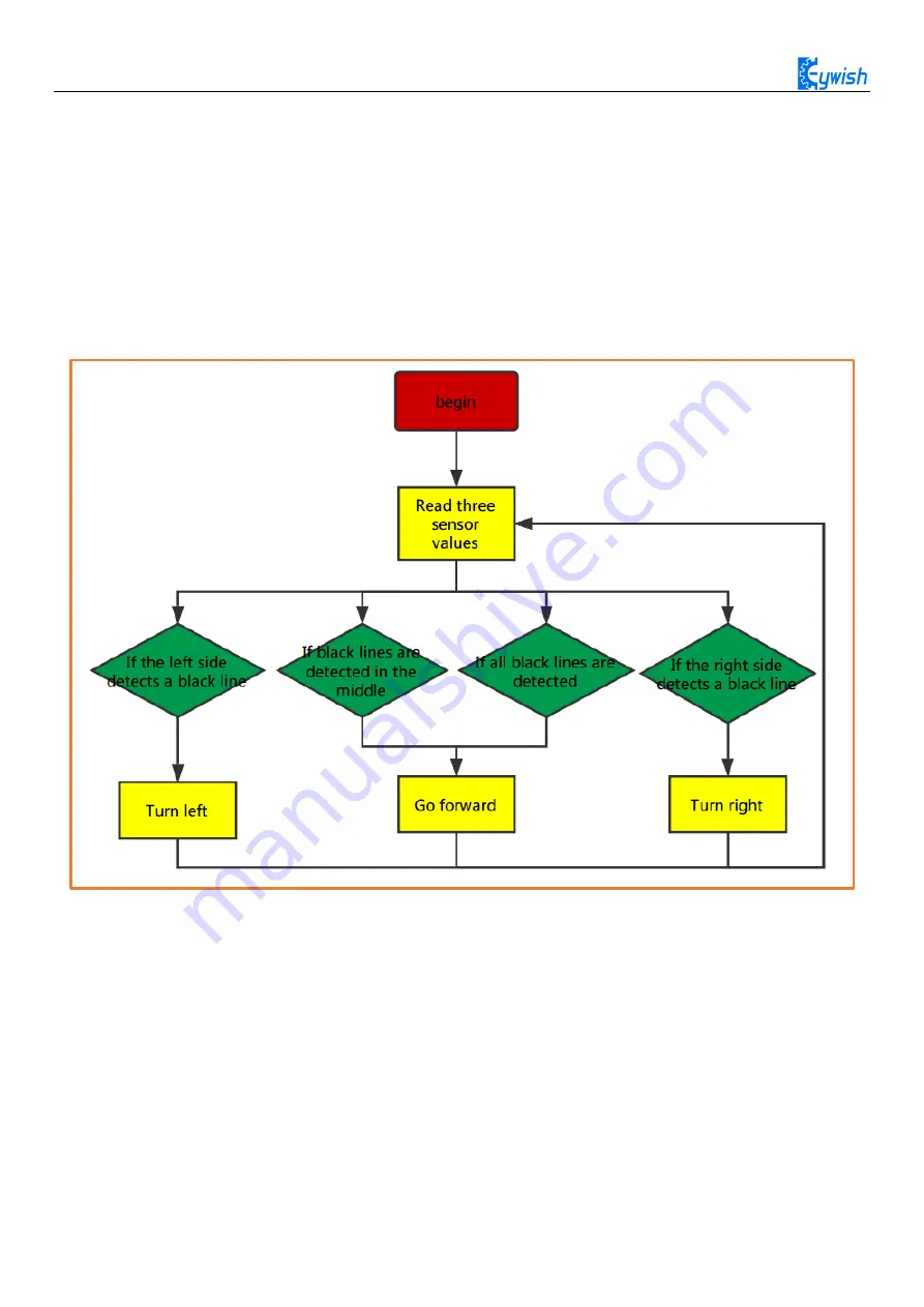
When the car enters the tracing mode, it keeps scanning the I/O port of the MCU connected to the sensors,
once detecting the changes in signal at the I/O port, the corresponding procedure will be implemented. If the
left sensor detects the black line, the car should turn the left; If the right sensor detects the black line, the car
should turn the right. After the direction adjustment, the car walks forward, and continues to detect the black
line repeatedly. The tracing flow chart is shown in Fig.3.2.23.
Figure .3.2.23 the Tracing Flow Chart
3.2.3.5.
2 Program Code
Code Path
“
hummer-bot\Lesson\ModuleDemo\InfraredTracing\ InfraredTracing.ino”
Summary of Contents for Hummer-Bot-1.0
Page 1: ...Hummer Bot 1 0 Instruction Manual V 2 0 ...
Page 18: ...15 Step4 You need to install motors Figure 3 1 5 Schematic diagram of motor installation ...
Page 50: ...47 Figure 3 2 15 Diagram of Data without Obstacles ...
Page 83: ...80 Test code Path hummer bot Lesson ModuleDemo IrkeyPressed IrkeyPressed ino ...


