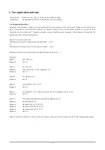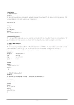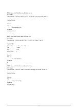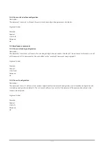
E.2.2 Extended status message
Description
Message Type 1
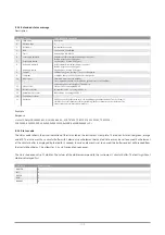
Extended status message
Pos Field
name
Description
0 Message
type
1
1 Hostname
Instrument
hostname
2
Date
Current date, YYY/MM/DD
3
Time
Current time, HH:MM:SS
4
Solar angle azimuth
Calculated solar azimuth/zenith angles in degrees.
North 0 degrees, east 90 degrees.
5
Solar angle zenith
Sky 0 degrees, horizon 90 degrees.
6
Axis angle azimuth
Actual azimuth/zenith axis angles in degrees.
North 0 degrees, east 90 degrees.
7
Axis angle zenith
Sky 0 degrees, horizon 90 degrees.
8
Latitude
Latitude in degrees. North positive, south negative.
9
Longitude
Longitude in degrees. East positive, west negative.
10
Air pressure
Estimated air pressure in millibar.
The estimation is based on the altitude, ground level of 1013 millibar
and atmospheric scale height of 7400 meters.
11
Status code
Status code. See paragraph E.2.3
12
Instrument status
Instrument status. See paragraph E.2.4
13
Azimuth motor status
Motor status. See paragraph E.2.5
14
Zenith motor status
15
Checksum
CRC-16 reverse bit order with seed of 0 and XOR polynomial of 0xA001. The checksum is
calculated over all characters till (not including) the first character of the checksum. The
value is in hexadecimal notation (0x<hex>).
Example
Response
.status=1;SolysGD140001;2014/10/28;14:26:24;-134.747698;75.851923;225.252365;75.851952;
51.996899;4.386230;999.36;0x044;0x00018234;0x210B;0x210B;0x6648;<LF>
E.2.3 Status code
The status code reflects the visual indication of the status led on the instrument’s rear plate. The led has 4 states (red, green, orange
and off). The instrument has a circular buffer with 3 elements, each element holds a led state or may be set to unused. Each element
of the circular buffer is displayed by the led for 1 second. In case an element is set to unused, the buffer readout will proceed from
the start without delay. This allows for 1, 2 and 3 second led sequences.
The status code consists of 3 nibbles. The values of the nibbles correspond to the instrument’s circular buffer. The least significant
nibble is displayed first.
Led state
Nibble value
UNUSED 0
OFF
1
GREEN 2
RED
3
ORANGE 4
108
Summary of Contents for SOLYS Gear Drive
Page 1: ...SOLYS2 Sun Tracker SOLYS Gear Drive Sun Tracker Instruction Manual...
Page 2: ...2...
Page 4: ...4...
Page 6: ...6...
Page 10: ...10...
Page 39: ...Figure 3 13 Adjustment of the sun sensor 21 0 5 mm 3x 39...
Page 61: ...6 Insert the Ethernet cable Contacts on this side 61...
Page 78: ...78...
Page 80: ...80...
Page 86: ...86...
Page 88: ...88...
Page 112: ......


