14
54-0215 Rev. C
Integrated Angle Data
When the Type bits indicate Integrated Angle data, the contents can be interpreted based
on the table below.
Table 6: Message Contents (Type Bits = Integrated Angle Data)
Bit(s)
Usage
Values
25, 24, 23 360
°
modulo counter
Increment when crossing from 359 to 0.
Decrement when crossing from 0 to 359.
Bit 25 is MSB; Power-up value is 0.
22 - 0
0 <= integrated angle < 360
LSB (bit 0) value is 42.91534
µ°.
3.1.3 Message
Rates
The rate at which the Rate or Integrated Angle information actually updates depends on
the application. Standard rate is 1000 Hz.
3.1.4 Synchronization
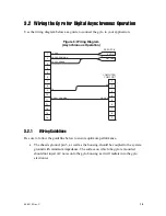
Message bits 29 and 30 make up the synchronization field for each message. These bits
conform to an eight-bit, continuously repeating pattern, as shown below.
1
st
Message
00
2
nd
Message
01
3
rd
Message
10
4
th
Message
11
This synchronization pattern allows you to design a receiver algorithm that can detect the
first byte of a message. For example, you could create a “state machine” with two modes:
Acquisition and Locked. In Acquisition mode, the state machine would examine the sixth
and seventh bits of each byte. Once it finds a byte position that exhibits the defined
synchronization pattern for 10 cycles in a row, and no other byte position has exhibited the
pattern for more than 3 of the last 10 cycles, the state machine would designate that byte
position as the first byte in the four-byte message. The state machine would then enter
Locked mode. In Locked mode, the state machine would continue to monitor each byte. If
the byte position that it designated as “first” does not match the synchronization pattern
for more than 3 out of 10 cycles, and a different byte position matches 7 or more, the state
machine would then designate the different byte position as the first byte.

