BT900-Sx Hardware Integration Guide
Intelligent BTv4.0 Dual Mode Module
Embedded Wireless Solutions Support Center:
http://ews-support.lairdtech.com
www.lairdtech.com/bluetooth
12
Americas: +1-800-492-2320
Europe: +44-1628-858-940
Hong Kong: +852 2923 0610
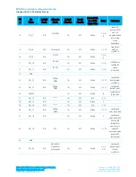
Pin
#
Pin
Name
Default
Funct.
Alternate
Funct.
Default
Direction
Supply
Domain
Internal Pull-
up or Pull-
down State
Notes
Comment
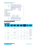
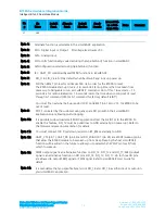
47
GND
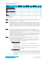
Note 1:
Alternate function is selectable in the
smar
tBASIC application.
Note 2:
DIO – Digital Input or Output. I/O voltage level tracks VCC.
Note 3:
AIN – Analog Input.
Note 4:
DIO or AIN functionality is selected using the GpioSetFunc() function in
smart
BASIC.
Note 5:
AIN configuration selected using GpioSetFunc() function.
Note 6:
I2C, UART, SPI controlled by xxxOPEN() functions in
smart
BASIC.
Note 7:
SIO_0 to SIO_3 are DIO by default when $autorun$ app runs on power up.
Note 8:
Pull the nRESET pin low for minimum 500 nS in order for the BT900 to reset.
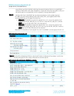
The BT900 module start-up time is ~1.6 seconds. Start-up time is the time taken from
power-up to being able to run a
smart
BASIC command. Out of this, 1.6 seconds, ~1.3
seconds is for radio initialisation. 1.6 seconds is also the time when coming out of reset
through AT command (ATZ) or AT command for factory default (at&f*).
You must fit an external pull-up resistor (10K) on nRESET (pin 16) to VCC for BT900 to be
out of reset.
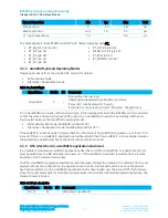
Note 9:
SPI CS is created by the customer using any spare SIO pin within their
smart
BASIC
application script allowing multi-dropping.
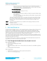
Note 10:
It is possible to download smart BASIC applications Over the Air (OTA) to the BT900. To
enable this feature, SIO_19 must be pulled low to GND externally (on power up). Refer to
the firmware release documentation for details.
Note 11:
You must connect 100 K pull-down resistor on BT_#SEL externally to GND.
Note 12:
UART_CTS (pin 1), UART_RX (pin 44) and SIO_20/ADC01 (pin 24) are WKUP (wake-up) pins
that allow the BT900 module to be woken up from Deep Sleep by the host.
smart
BASIC
function will be added in the future to allow you to select which WKUP pin (or all) from
which to wake up.
Note 13:
PWM output signal is an alternative function on SIO_12, SIO_13 and SIO_17. FREQ output
signal is an alternative function on SIO pins SIO_12, SIO_13, SIO_17. Up to three SIO pins
are allowed to output FREQ signal or PWM signal. Refer to
smart
BASIC User Guide for
details.
Note 14:
It is mandatory that you specifically set script SIO_14 and SIO_16 as either input or output in
your
smart
BASIC application.

