BT900-Sx Hardware Integration Guide
Intelligent BTv4.0 Dual Mode Module
Embedded Wireless Solutions Support Center:
http://ews-support.lairdtech.com
www.lairdtech.com/bluetooth
28
Americas: +1-800-492-2320
Europe: +44-1628-858-940
Hong Kong: +852 2923 0610
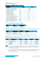
SIO pin direction
For BT900 modules shipped from production with
smart
BASIC runtime engine firmware, most SIO pins
(with a default function of DIO) are digital inputs (see
). Remember to change the direction SIO
pin (in your
smart
BASIC application script) if that particular pin is wired to a device that expects to be
driven by the BT900 SIO pin configured as an output. Also, SIO pins that are inputs are set in firmware
by default to have internal pull-up resistor enabled (on SIO_xx pins, not BT_xxxx pins). You may
configure this in your
smart
BASIC application script.
Note: The internal pull-up takes current from VCC.
Lowest power consumption is achieved when all SIO pins are set as outputs and low.
SIO_19 pin and VSP Command
SIO_19 pin must be pulled to GND externally to enable VSP (virtual serial Port) Command mode for
BLE. SIO_19 is an input, set with internal pull-up in the firmware. VSP Command mode is used to load
smartBASIC scripts OTA (over the air) from a BLE-enabled host.
nRESET pin (active low)
Hardware reset. Wire out to push button or drive by host.
By default, the module is out of reset (internal weak-pull-up) when power is applied to the VCC pin.
You MUST fit an external pull-up resistor (10K) on nRESET (pin 16) to VCC for the BT900 to be out of
reset. nRESET needs to be held low (0V)for greater than 500nS to reset the module.
6.2
PCB Layout on Host PCB - General
PCB Checklist
You
MUST
place the BT900-Sx module close to the edge of PCB (mandatory for BT900-SA for on-board
chips antenna to radiate properly).
Use solid GND plane on the inner layer (for best EMC and RF performance).
All module GND pins MUST be connected to host PCB GND.
Place GND vias as close to module GND pads as possible.
Unused PCB area on surface layer can be flooded with copper but place GND vias regularly to connect
copper flood to inner GND plane. If GND, flood copper underside the module then connect with GND
vias to inner GND plane.
Route traces to avoid noise being picked up on VCC supply and AIN (analogue) and SIO (digital) traces.
Do
NOT
run any track near pin 34 of the BT900-Sx.
Ensure no exposed copper is on the underside of the module (refer to land pattern of BT900
development board).
6.3
PCB Layout on Host PCB for BT900-SA
6.3.1
Antenna keep-out on host PCB
The BT900-SA has an integrated chip antenna and its performance is sensitive to host PCB. It is critical to
locate the BT900-SA on the edge of the host PCB (or corner) to allow the antenna to radiate properly. Refer
to guidelines in section
Host PCB Land Pattern and Antenna Keep-out for BT900-SA
. Some of those
guidelines are repeated below.
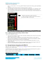
Ensure there is no copper in the antenna keep-out area on any layers of the host PCB. Keep all
mounting hardware and metal clear of the area to allow proper antenna radiation.
For best antenna performance, place the BT900-SA module on the edge of the host PCB, preferably in
the corner with the antenna facing the corner.
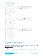
The BT900 development board has the BT900-SA module on the edge of the board (not in the corner).
The antenna keep-out area is defined by the BT900 development board which was used for module
development and antenna performance evaluation is shown in
, where the antenna keep-out


