BT900-Sx Hardware Integration Guide
Intelligent BTv4.0 Dual Mode Module
Embedded Wireless Solutions Support Center:
http://ews-support.lairdtech.com
www.lairdtech.com/bluetooth
13
Americas: +1-800-492-2320
Europe: +44-1628-858-940
Hong Kong: +852 2923 0610
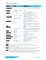
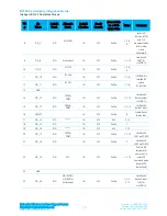
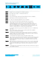
Note 15:
smart
BASIC runtime engine firmware (9.2.1.0) has DIO (default function) input pins that are
PULL-UP enabled by default. You can disable internal PULL_UP through your
smart
BASIC
application script All the SIO pins (with a default function of DIO) are mostly inputs (unless
stated otherwise in
) – with no internal pull-up. SIO_1 and SIO_2 are outputs:
- SIO_1 (alternative function UART_TX) is an output, set high (in FW)
- SIO_2 (alternative function UART_RTS) is an output, set low (in FW)
- SIO_0 (alternative function UART_RX) is an input, set with internal
- SIO_3 (alternative function UART_CTS) is an input, set with internal pull-up
- SIO_19 is an input, needs an external pull-down. It is used for download
smart
BASIC
applications over-the-air. See the latest FW release documentation for details.
Lowest Power consumption is achieved when all SIO pins are set as outputs and low.
Note 16:
Note 17:
1.8V operation not supported in current
smart
BASIC runtime engine FW v9.1.2.0) hence
Customer must operate BT900 from nominal 3.3V supply (2.8-3.6V, refer to Table4, note4)
for how to operate BT900 from 3.3V. Basically connect the external 3.3V supply to pin 31
(BT_VREG_IN_HV), pin 5 (VCC), and pin 43 (BT_VDD_IO). Customer MUST leave pin 32
(BT_VREG_OUT_HV) unconnected.
Dedicated BT900 BT-WiFi coexistence pins for CSR scheme Unity3 (used for classic BT) and
Unity3e (used for BLE). Refer to
smart
BASIC user manual for details on how to enable
coexistence.
The BT900 module is delivered with the integrated
smart
BASIC runtime engine FW loaded (but no onboard
smart
BASIC application script). Because of this, it starts up in AT command mode by default.
At reset, all SIO lines are configured as the defaults shown above.
SIO lines can be configured through the
smart
BASIC application script to be either inputs (with pull-ups or
none) or outputs. When an alternative SIO function is selected (such as I2C or SPI), the firmware does not
allow the setup of internal pull-up. Therefore, when I2C interface is selected, pull-up resistors on I2C SDA
and I2C SCL MUST be connected externally as per I2C standard.
UART_RX, UART_TX, UART_CTS are 3.3 V level logic (if VCC is 3.3 V, i.e. SIO pin I/O levels track VCC). For
example, when RX and TX are idle, they sit at 3.3 V (if VCC is 3.3 V). Conversely, handshaking pins CTS and
RTS at 0 V are treated as assertions.
Pin 3 (nAutoRUN) is an input, with active low logic. In the development kit (DVK-BT900-sx) it is connected so
that the state is driven by the host’s DTR output line. The nAutoRUN pin must be externally held high or low
to select between the following two BT900 operating modes:
Self-contained Run mode (nAutoRUN pin held at 0 V).
Interactive / development mode (nAutoRUN pin held at VCC).
smart
BASIC runtime engine firmware checks for the status of nAutoRUN during power-up or reset. If it is low
and if there is a
smart
BASIC application script named $autorun$, then the
smart
BASIC runtime engine FW
executes the application script automatically; hence the name S
elf-contained Run Mode
.
3.3
Electrical Specifications
3.3.1
Absolute Maximum ratings
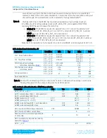
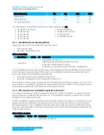
Absolute maximum ratings for supply voltage and voltages on digital and analogue pins of the module are
listed below. Exceeding these values causes permanent damage.
The average SIO pin output current is defined as the average current value flowing through any one of the
corresponding pins for a 100mS period. The total average SIO pin output current is defined as the average

