SCXI-1122 Calibration Procedure
14
ni.com
•
volt1
and
volt2
—The first and second calibrator voltage readings
for the gain values you are saving on the SCXI-1122 module
•
binary1
and
binary2
—The first and second binary readings for
the gain values you are saving on the SCXI-1122 module
•
calConst1
and
calConst2
—These are return values
Repeat this step with
calibrationArea
set to 1, and then again with
calibrationArea
set to 3.
2.
Repeat step 1 for all remaining gain values.
You have now finished adjusting the calibration constants of the
SCXI-1122 module.
Adjusting Excitation Limits
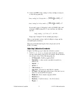
Complete the following steps to adjust the excitation limits:
1.
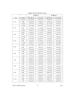
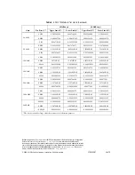
Refer to Table 2 for the specific limits to test.
2.
Ensure that the E Series DAQ device is connected to the SCXI-1122
module.
3.
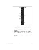
Connect a 15
Ω
resistor to the VEX+ and VEX– pins, which make up
the voltage excitation channel.
Note
If you are not using the SCXI-1322 terminal block, make sure that the SENSE+
terminal is connected to the VEX+ terminal and the SENSE– terminal to the VEX–
terminal.
4.
Set the DMM to voltage mode and connect it across the 15
Ω
load.
5.
Measure the voltage and use the measurement as
calConst2
.
6.
Set the DMM to DC current mode and connect it across the current
excitation channel (pin IEX+ and IEX–).
7.
Measure the DC current and use the measurement as
calConst1
.
8.
Call
SCXI_Cal_Constants
to create and store the new calibration
constants. Set the following parameters:
•
SCXIchassisID
—The ID assigned by MAX
•
ModuleSlot
—1, unless the module is in a different slot
•
channel
— –2
•
opCode
—3
•
calibrationArea
—0
•
rangeCode
—0 (not used for the SCXI-1122 module)
•
SCXIgain
—0
•
DAQboard
—Device number assigned by MAX


