123
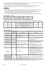
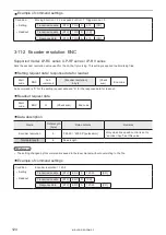
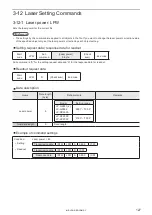
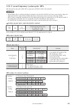
3-11 On-the-fly Marking Commands
3-11-1 Motion settings: TRG
Supported model: LP-RC series / LP-RF series / LP-RV series
Sets the basic configuration of the on-the-fly marking, such as moving direction and etc. The settings are applied to all
marking files.
⿎
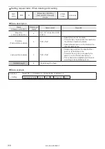
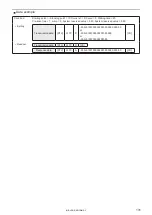
Setting request data / response data for readout
Start
code
TRG
Sub
command
[Moving direction] [Line speed control]
[Trigger mode]
3-byte
(Check
sum)
End code
Sub command is “S” for the setting request data and “A” for the response data for readout.
⿎
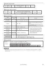
Readout request data
Start
code
TRG
R
(Check sum)
End code
⿎
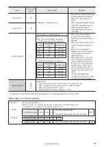
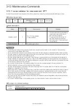
Data description
Name
Data length
[byte]
Data contents
Remarks
Moving direction
1
“0”: Marking to static object
“1”: +X to -X (Left)
“2”: -X to +X (Right)
“3”: +Y to -Y (Front)
“4”: -Y to +Y (Back)
• Specify “0” to disable on-the-fly
marking.
• The direction of X/Y axis is defined by
the head direction setting in System
settings.
Line speed control
1
“0”: Fixed speed
“1”: Encoder input
With LP-400/V compatible command
mode, “2 sensors input” cannot be set and
readout.
Trigger mode
1
“0”: Single trigger
“1”: Marking at regular intervals
• “Single trigger” corresponds to “trigger
marking” of LP-400/LP-V series.
• With LP-400/V compatible command
mode, “multiple triggers” cannot be set
and readout.
Total data length
3
Fixed length.
ンㄆㄇㄆㄓㄆㄏㄆ
• Any of the following functions that are not available with on-the-fly marking are configured.
• Link control with external image checkers
• Overwriting interval
• Skip marking of 2D code (Setting of module marking order)
• When the trigger mode is set to Marking at regular intervals, those functions are also not available.
• Registered characters (via I/O)
• External Offset including SEO command
• Characters specified by SIN command
• Counter reset at date change
• The setting changed by this command is saved in the laser marker without overwriting to the file.
• The “Delay distance” which was specified in LP-400/V series is corresponding to “Trigger detecting position” and
“Workpiece reference boundary” in this product. If you want to set those parameters, switch the command mode to the
standard mode by RMS command.
ME-LP-GS-SR-COMP-3
Summary of Contents for LP-GS Series
Page 11: ...1 Preparation of Command Control ME LP GS SR COMP 3...
Page 26: ...2 Communication Control Basics ME LP GS SR COMP 3...
Page 50: ...3 Data Format for Each Command ME LP GS SR COMP 3...
Page 136: ...136 MEMO ME LP GS SR COMP 3...
Page 137: ...Troubleshooting ME LP GS SR COMP 3...
Page 163: ...Character Code Table ME LP GS SR COMP 3...
Page 176: ...Index ME LP GS SR COMP 3...
Page 178: ...178 W Warning 154 ME LP GS SR COMP 3...
Page 179: ......
Page 180: ...Panasonic Industrial Devices SUNX Co Ltd 2014 2019 April 2019...


