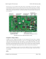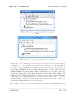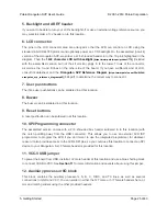
shared by the user pushbuttons and the green user LED. You can print to the LCD using the functions
in the
OrangutanLCD
[https://www.pololu.com/docs/0J18/5]
section of the Pololu AVR C/C++ Library.
The LCD’s backlight can be turned off by driving the BACKLIGHT line low. Adjustable dimming of the
LCD can be achieved by connecting the line to a free PWM output.
The AVR’s AREF pin is available next to the backlight pin.
Pushbuttons
The Orangutan SVP has five total pushbuttons: a
power on/off button
located on the right side of the
bottom edge of the board, a
reset button
located on the left side of the top edge of the board, and
three user pushbuttons
located along the left edge of the board. Please note that the power button
disconnects the external power supply from the entire board, while the reset button connects directly
to the AVR’s RESET pin and does not disconnect the power supply.
The user pushbuttons, from top to bottom, are on pins PC5, PC3, and PC2. Pressing one of these
buttons pulls the associated I/O pin to ground through a resistor. You can detect button pushes using
the functions in the
OrangutanPushbuttons
[https://www.pololu.com/docs/0J18/9]
section of the Pololu
AVR C/C++ Library. The library takes care of configuring the pins as inputs, enabling the AVR’s internal
pull-up resistors, and debouncing (accounting for the fact that pushbuttons physically bounce when
pressed).
Buzzer
The Orangutan SVP comes with a buzzer controlled by pin PD4. If you alternate between driving the
buzzer pin high and low at a given frequency, the buzzer will produce sound at that frequency. You can
use the functions in the
OrangutanBuzzer
[https://www.pololu.com/docs/0J18/3]
section of the Pololu AVR
C/C++ Library to play notes in the background (using hardware PWM) while the rest of your processor
performs other tasks.
Trimpot
The Orangutan SVP comes with a 10 kilo-ohm user trimmer potentiometer, located between the
USB connector and the LCD connector. The trimpot is connected to the auxiliary processor, which
measures its output voltage and reports it to the AVR.
You can disconnect the trimpot from the auxiliary processor by cutting the labeled trace between POT
and ADC/SS on the bottom side of the board. This gives you two options for that line: you can use it
as a general-purpose analog input by connecting some other output to it, or you can connect it to one
of your AVR’s free I/O lines and use it as the SPI slave-select line for the auxiliary processor, allowing
you to communicate with some other SPI peripheral.
Pololu Orangutan SVP User’s Guide
© 2001–2019 Pololu Corporation
4. Module Pinout and Components
Page 11 of 43


