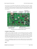
Programming Connector
The Orangutan SVP has a 6-pin programming connector on the upper left side. This gives you the
option of using an AVR ISP in-system programmer from Atmel or a compatible programmer, such
as our
Pololu USB AVR Programmer
[https://www.pololu.com/product/1300]
to program the AVR. This is
not necessary, though, because the Orangutan SVP’s auxiliary processor can serve as an AVR ISP
programmer for the AVR.
By default, pin 5 of the Programming connector, which is labeled by an asterisk (*), is connected to
the AVR’s RESET line, which is necessary for ISP programming by an external device). However, you
can disconnect those two pins by cutting a labeled trace on the bottom of the circuit board. This gives
you the option of using that line for some other signal.
Auxiliary I/O & Power Outputs
The Orangutan SVP has five auxiliary I/O lines that are connected to the auxiliary processor. Each
I/O line has associated power and ground connections for easy connections to sensors: the exterior
(top) pin is ground, the middle pin is power (VCC), and the interior (bottom) pin is signal and connects
directly to an auxiliary processor I/O line. The
TX
line is the serial transmit line. It transmits TTL-level
serial bytes received from the computer on the “Pololu Orangutan SVP TTL Serial Port”. The lines
A
,
B
,
C
, and
D/RX
can be configured to do different things. They can function as three analog inputs
plus a serial receive line, as four analog inputs, or as the inputs for two quadrature encoders. See the
OrangutanSVP
[https://www.pololu.com/docs/0J18/13]
section of the Pololu AVR C/C++ Library for more
information.
Servo Demultiplexer
The hardware in the upper-right corner of the Orangutan SVP allows you to control up to 8 servos
without sacrificing a large number of I/O lines or processor cycles. You can control servos using the
functions in the
OrangutanServos
[https://www.pololu.com/docs/0J18/11]
section of the Pololu USB AVR
C/C++ library.
The input signal of the demultiplexer is connected to pin PD5 on the AVR. If you are not using PD5 to
control servos, you can use it as a general-purpose digital I/O line or PWM output.
The three output-selection pins of the multiplexer (
SA
,
SB
, and
SC
) are available in the header near
the multiplexer so they can be wired to free I/O lines on the AVR, allowing you to switch between
servos. The output-selection pins have pull-down resistors, so if you have four servos or fewer you
can leave some of them disconnected.
The eight output pins of the multiplexer are available in two 4×3 headers. These lines have current-
limiting resistors on them. Each multiplexer output line has associated power and ground connections
for easy connections to the servos: the exterior (top) pin is ground, the middle pin is power. For each
Pololu Orangutan SVP User’s Guide
© 2001–2019 Pololu Corporation
4. Module Pinout and Components
Page 12 of 43


