background image

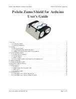
Pololu Zumo Shield for Arduino

User's Guide

1. Overview  .  .  .  .  .  .  .  .  .  .  .  .  .  .  .  .  .  .  .  .  .  .  .  .  .  .  .  .  .  .  .  .  .  .  .  .  .  .  .  .  .  .  .  .  .  .  .  .  .  .  .  .  .  .  2

1.a. Contacting Pololu  .  .  .  .  .  .  .  .  .  .  .  .  .  .  .  .  .  .  .  .  .  .  .  .  .  .  .  .  .  .  .  .  .  .  .  .  .  .  .  .  .  .  .  .  .  .  3
1.b. Included components  .  .  .  .  .  .  .  .  .  .  .  .  .  .  .  .  .  .  .  .  .  .  .  .  .  .  .  .  .  .  .  .  .  .  .  .  .  .  .  .  .  .  .  .  3

2. Assembly  .  .  .  .  .  .  .  .  .  .  .  .  .  .  .  .  .  .  .  .  .  .  .  .  .  .  .  .  .  .  .  .  .  .  .  .  .  .  .  .  .  .  .  .  .  .  .  .  .  .  .  .  .  .  5

2.a. What you will need  .  .  .  .  .  .  .  .  .  .  .  .  .  .  .  .  .  .  .  .  .  .  .  .  .  .  .  .  .  .  .  .  .  .  .  .  .  .  .  .  .  .  .  .  .  5
2.b. Assembling the Zumo Shield and chassis .  .  .  .  .  .  .  .  .  .  .  .  .  .  .  .  .  .  .  .  .  .  .  .  .  .  .  .  .  .  .  .  .  .  6
2.c. Adding a Zumo reflectance sensor array (optional) .  .  .  .  .  .  .  .  .  .  .  .  .  .  .  .  .  .  .  .  .  .  .  .  .  .  .  .  . 16

3. The Zumo Shield in detail  .  .  .  .  .  .  .  .  .  .  .  .  .  .  .  .  .  .  .  .  .  .  .  .  .  .  .  .  .  .  .  .  .  .  .  .  .  .  .  .  .  .  .  .  . 22

3.a. Features and components  .  .  .  .  .  .  .  .  .  .  .  .  .  .  .  .  .  .  .  .  .  .  .  .  .  .  .  .  .  .  .  .  .  .  .  .  .  .  .  .  .  . 22
3.b. Front expansion  .  .  .  .  .  .  .  .  .  .  .  .  .  .  .  .  .  .  .  .  .  .  .  .  .  .  .  .  .  .  .  .  .  .  .  .  .  .  .  .  .  .  .  .  .  .  . 24
3.c. Jumper settings  .  .  .  .  .  .  .  .  .  .  .  .  .  .  .  .  .  .  .  .  .  .  .  .  .  .  .  .  .  .  .  .  .  .  .  .  .  .  .  .  .  .  .  .  .  .  . 25
3.d. 3-axis compass module (accelerometer and magnetometer)  .  .  .  .  .  .  .  .  .  .  .  .  .  .  .  .  .  .  .  .  .  .  .  . 26

4. Schematic diagrams  .  .  .  .  .  .  .  .  .  .  .  .  .  .  .  .  .  .  .  .  .  .  .  .  .  .  .  .  .  .  .  .  .  .  .  .  .  .  .  .  .  .  .  .  .  .  .  . 28
5. Arduino pin assignment table  .  .  .  .  .  .  .  .  .  .  .  .  .  .  .  .  .  .  .  .  .  .  .  .  .  .  .  .  .  .  .  .  .  .  .  .  .  .  .  .  .  .  . 29
6. Zumo Shield Arduino Libraries  .  .  .  .  .  .  .  .  .  .  .  .  .  .  .  .  .  .  .  .  .  .  .  .  .  .  .  .  .  .  .  .  .  .  .  .  .  .  .  .  .  . 30
7. Example projects  .  .  .  .  .  .  .  .  .  .  .  .  .  .  .  .  .  .  .  .  .  .  .  .  .  .  .  .  .  .  .  .  .  .  .  .  .  .  .  .  .  .  .  .  .  .  .  .  .  . 32

7.a. RC Zumo  .  .  .  .  .  .  .  .  .  .  .  .  .  .  .  .  .  .  .  .  .  .  .  .  .  .  .  .  .  .  .  .  .  .  .  .  .  .  .  .  .  .  .  .  .  .  .  .  .  . 32
7.b. Simple border-detecting sumo robot  .  .  .  .  .  .  .  .  .  .  .  .  .  .  .  .  .  .  .  .  .  .  .  .  .  .  .  .  .  .  .  .  .  .  .  . 33
7.c. Maze solver  .  .  .  .  .  .  .  .  .  .  .  .  .  .  .  .  .  .  .  .  .  .  .  .  .  .  .  .  .  .  .  .  .  .  .  .  .  .  .  .  .  .  .  .  .  .  .  .  . 34
7.d. Using the compass  .  .  .  .  .  .  .  .  .  .  .  .  .  .  .  .  .  .  .  .  .  .  .  .  .  .  .  .  .  .  .  .  .  .  .  .  .  .  .  .  .  .  .  .  . 34

8. Controlling a servo  .  .  .  .  .  .  .  .  .  .  .  .  .  .  .  .  .  .  .  .  .  .  .  .  .  .  .  .  .  .  .  .  .  .  .  .  .  .  .  .  .  .  .  .  .  .  .  .  . 36

8.a. Controlling a servo with an Arduino Uno .  .  .  .  .  .  .  .  .  .  .  .  .  .  .  .  .  .  .  .  .  .  .  .  .  .  .  .  .  .  .  .  .  . 36
8.b. Controlling a servo with an Arduino Leonardo  .  .  .  .  .  .  .  .  .  .  .  .  .  .  .  .  .  .  .  .  .  .  .  .  .  .  .  .  .  .  . 37

Pololu Zumo Shield for Arduino User's Guide

© 2001–2013 Pololu Corporation

http://www.pololu.com/docs/0J57/all

Page 1 of 38

Summary of Contents for Zumo Shield

Page 1: ...umper settings 25 3 d 3 axis compass module accelerometer and magnetometer 26 4 Schematic diagrams 28 5 Arduino pin assignment table 29 6 Zumo Shield Arduino Libraries 30 7 Example projects 32 7 a RC Zumo 32 7 b Simple border detecting sumo robot 33 7 c Maze solver 34 7 d Using the compass 34 8 Controlling a servo 36 8 a Controlling a servo with an Arduino Uno 36 8 b Controlling a servo with an Ar...

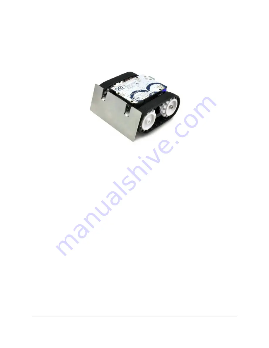
Page 2: ...led Zumo robot with a Zumo Shield Arduino Uno and Zumo blade A Zumo chassis Zumo Shield and Arduino can be combined to become a low profile Arduino controlled tracked robot that is less than 10 cm on each side small enough to qualify for Mini Sumo competitions Zumo Shield for Arduino labeled top view Zumo robot assembled with a Zumo Shield and Arduino Uno back view The Zumo Shield is available by ...

Page 3: ... a stainless steel Zumo blade http www pololu com catalog product 1410 or as a fully assembled Zumo robot for Arduino http www pololu com catalog product 2506 with 75 1 HP motors http www pololu com catalog product 2361 and a reflectance sensor array http www pololu com catalog product 1419 installed Zumo Shield The shield itself comes with the following components right angle slide switch two pus...

Page 4: ...el this masking off to expose the acrylic surface or you can leave it on to increase the thickness of the plates The shield and chassis kit include extra parts like jumper wires screws nuts and washers so do not be concerned if you have some leftover hardware after assembling your Zumo Zumo Robot for Arduino The Zumo robot for Arduino is a fully assembled robot platform built from the same compone...

Page 5: ... product 2361 or 50 1 http www pololu com catalog product 998 gear ratio versions with HP motors The pre assembled version of the Zumo robot http www pololu com catalog product 2506 includes two 75 1 HP micro metal gearmotors An Arduino we recommend an Uno R3 http www pololu com catalog product 2191 or a Leonardo http www pololu com catalog product 2192 Four AA batteries we recommend rechargeable ...

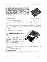
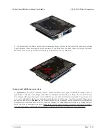
Page 6: ...duino boards including the Uno R3 and the Leonardo use one 1 10 header two 1 8 headers and one 1 6 header older Arduino boards use two 1 8 headers and two 1 6 headers the two pairs of pins highlighted above in red should not be populated if you are using this board with an older Arduino that does not support these additional pins Please make sure you solder the appropriate headers for your particu...

Page 7: ...ne later though soldering to these pins is more difficult once the robot is assembled especially if you decide later you want to add header pins for use with shorting blocks this would require a lot of disassembly The jumpers are explained in detail in Section 3 c The buzzer and battery level jumpers can be connected by soldering in a short piece of wire between the two holes while the compass I C...

Page 8: ... components in the outermost three rows of the front expansion area can extend below the board the fourth front expansion row can only be used for pins extending above the board and if you add any through hole parts to the prototyping areas on the shield you will need to drill corresponding holes in the acrylic spacer plate for the leads to fit into Motors 7 Cut two of the included jumper wires in...

Page 9: ...closest to the front so you should attach the leads to allow the motors to be oriented this way However don t worry if you accidentally get the orientation of one or both motors wrong You can later compensate for it in software with our ZumoMotors library http www pololu com docs 0J57 6 9 Place the motors into the channel in the front of the chassis aligning the gearbox with the grooves in the cha...

Page 10: ... the through holes in the shield resting on top of it There is only one correct orientation for these plates The plate consists of two separate pieces to make it possible to disassemble the Zumo without having to desolder the motors or battery terminals 13 In each of the four mounting holes insert a 2 56 machine screw through the shield spacer plate and chassis and tighten it against a nut under t...

Page 11: ... place them on top of the shield so that the holes line up with the two front mounting holes and insert the two longer 5 16 2 56 machine screws included with the shield through the blade shield spacer plate and chassis Be careful when adjusting the angle of the sumo blade while it is mounted to the chassis as this can crack the acrylic spacer plate if you apply sudden or excessive force We recomme...

Page 12: ...ts as shown in the picture below Note that the two individual contacts should be inserted into the chassis so that their solder tabs protrude through the holes in the top of the chassis Pololu Zumo Shield for Arduino User s Guide 2001 2013 Pololu Corporation 2 Assembly Page 12 of 38 ...

Page 13: ...e below Sprockets and track 17 Place an idler sprocket on each shoulder bolt followed by a washer The side of the sprocket with teeth should face the same direction as the threaded end of the bolt so that the teeth end up pointing in towards the chassis 18 Insert the shoulder bolts through the side of the chassis into the nut Use a 3 mm hex key Allen wrench to tighten the bolts until the washers a...

Page 14: ...h with the outside of the sprocket A good way to accomplish this is to set the wheel on a table top and press the motor shaft into the wheel until it contacts the table 20 At this point you can add the silicone tracks by stretching them around the sprockets on each side of the chassis Your Zumo Shield and chassis are now complete just add batteries and an Arduino to get your Zumo robot moving Polo...

Page 15: ...areful effort 1 Remove the tracks from the chassis and carefully pull the drive sprockets off the motors 2 Remove the battery cover and batteries from the chassis 3 Unscrew all four sets of machine screws and nuts holding the shield to the chassis Pololu Zumo Shield for Arduino User s Guide 2001 2013 Pololu Corporation 2 Assembly Page 15 of 38 ...

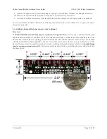
Page 16: ...catalog product 1419 is an easy way to add line following and edge detection capabilities to the Zumo robot It is designed specifically to mount to the front expansion area of the Zumo shield and it includes everything you need for installation Note that the reflectance sensor array is not included with the Zumo shield or Zumo Robot Kit and the Zumo robot can be used without it For more informatio...

Page 17: ...We recommend using the right angle header mounted as shown in the picture below but the straight 3 pin header will also work if you do not have anything already soldered to the Zumo shield s front expansion area that would interfere If you choose to install this header please make sure you are doing it in a way that will not prevent installation of the sensor array e g by installing it on the wron...

Page 18: ...ard and these are the only pins that need to be soldered though it is fine to solder all 24 pins Connecting to the Zumo shield The 2 12 female header included with the reflectance sensor array should be soldered to the front expansion area of the Zumo shield so that it is centered in the expansion area and flush with the Zumo chassis rows 2 and 3 With the female header in place the assembled senso...

Page 19: ...ault pinout simply call init with no arguments reflectanceSensors init If you opt to leave off the LEDON shorting block you should use the QTR_NO_EMITTER_PIN initialization parameter reflectanceSensors init QTR_NO_EMITTER_PIN Otherwise the library code will still be trying to do something with the emitter pin A4 or 2 depending on which Arduino you are using and this would interfere with your being...

Page 20: ...no I O line and the left hole connects to sensor There is a single trace on the component side of the PCB between the two holes of each pair and this trace can be cut to disable the sensor and free up the I O line The proper place to cut is marked on the silkscreen by carets For example if you want to use your Zumo for solving a line maze you can likely get by with just four sensors you can use th...

Page 21: ...th this approach If you later decide you want to re enable those sensors you can connect across the cut trace with a wire or you can use a wire to remap the sensor to a different pin The following example shows how you could re enable the A2 sensor and remap the A3 sensor to pin A5 instead To configure the ZumoReflectanceSensorArray library to use this remapped configuration call init with these a...

Page 22: ...ctor on the left is indicated by a plus sign A charger like the iMAX B6AC http www pololu com catalog product 2260 connected by clipping its alligator clips to a pair of jumper wires inserted into the charge connector works well for charging the Zumo After passing through reverse protection the battery voltage is connected to the rest of the shield by the power switch The switched battery voltage ...

Page 23: ...cted to digital pin 12 on the Arduino pressing the button pulls the pin low The Pushbutton library included with our Zumo Shield libraries http www pololu com docs 0J57 6 makes it easy to detect and debounce button presses with this pushbutton Motor driver An integrated DRV8835 http www pololu com catalog product 2135 dual motor driver on the Zumo Shield drives the Zumo s two micro metal gearmotor...

Page 24: ...d 0J592 552k pdf The front expansion makes available digital pins 2 4 5 and 11 and analog pins A0 through A5 It also provides access to the two I C pins SDA and SCL However please note that the I C pins are not independent pins they are respectively duplicates of analog pins A4 and A5 on the Uno R3 and digital pins 2 and 3 on the Leonardo Typically you will only be able to use these pins for eithe...

Page 25: ...per settings The Zumo shield has several jumpers that let you change the way it is connected to the Arduino as shown in the picture below The battery level jumper connects the Arduino s analog pin 1 to a voltage divider circuit that allows you to monitor the Zumo s battery voltage This jumper is disconnected by default and can be connected by soldering a short length of wire between the two holes ...

Page 26: ...he most convenient place to do this is in the front expansion area where these pins are all located together as indicated by the light blue boxes in the picture above More details about the 3 axis compass module can be found in Section 3 d Instead of making a wire connection you can solder a 1 3 male header to the buzzer control jumper holes to allow the use of a shorting block for connecting the ...

Page 27: ...angle instead of just timing how long to run the motors to make such a turn We have written a basic LSM303 Arduino library https github com pololu LSM303 that makes it easier to interface the LSM303DLHC with an Arduino as well as an example project http www pololu com docs 0J57 7 d that demonstrates how to use the compass to help the Zumo coordinate its turns In our tests we found that the batteri...

Page 28: ...d are available as a downloadable PDF Zumo Shield schematic diagrams http www pololu com file download zumo_shield_schematic pdf file_id 0J591 121k pdf Pololu Zumo Shield for Arduino User s Guide 2001 2013 Pololu Corporation 4 Schematic diagrams Page 28 of 38 ...

Page 29: ...tion control line 9 right motor PWM control line 10 left motor PWM control line 11 digital I O front expansion 12 digital I O user pushbutton pressing pulls low 13 digital I O yellow user LED high turns LED on Analog pins Zumo Shield function Notes alternate functions A0 analog input and digital I O front expansion A1 analog input and digital I O front expansion optional jumper to battery level vo...

Page 30: ...directions in your code ZumoBuzzer The ZumoBuzzer library provides functions that allow various sounds to be played on the buzzer of the Zumo Shield from simple beeps to complex tunes See Section 3 for more details about the buzzer and Section 3 c for an explanation of the buzzer control jumper settings The ZumoBuzzer library is fully compatible with the OrangutanBuzzer http www pololu com docs 0J...

Page 31: ...tance sensors http www pololu com catalog category 123 Since the Zumo reflectance sensor array http www pololu com catalog product 1419 has the same interface as the QTR RC reflectance sensors the ZumoReflectanceSensorArray library uses QTRSensors to read the sensor array Pololu Zumo Shield for Arduino User s Guide 2001 2013 Pololu Corporation 6 Zumo Shield Arduino Libraries Page 31 of 38 ...

Page 32: ...braries http www pololu com docs 0J57 6 installed the sketch file can be opened in Arduino by selecting File Examples ZumoExamples RCControl A Zumo robot with an RC receiver attached to make a radio controlled vehicle An easy way to connect the receiver to the Zumo Shield is to solder two 1 3 male header strips http www pololu com catalog product 966 to the locations shown in the diagram below the...

Page 33: ...s are colored black with a white border around the edge infrared reflectance sensors like our QTR sensors http www pololu com catalog category 123 are great for this purpose The Zumo Reflectance Sensor Array http www pololu com catalog product 1419 conveniently mounts six of these sensors in a module designed to plug directly into the front expansion header of the Zumo Shield note the pre assemble...

Page 34: ..._SPEED and or TURN_DURATION If you do not hear any sound from the buzzer make sure you have the buzzer control jumper http www pololu com docs 0J57 3 c configured correctly for your Arduino The ability to wander around while staying inside a sumo ring is enough to allow a Zumo to compete as a basic sumo robot but a more advanced robot might be able to detect its opponent and drive toward it direct...

Page 35: ...he magnetometer assuming that the robot is always level In order to prevent external locally varying magnetic fields e g from rebar in a concrete floor from affecting the Zumo s navigation too much the program measures the magnetic heading before each turn then turns ninety degrees relative to that heading Pololu Zumo Shield for Arduino User s Guide 2001 2013 Pololu Corporation 7 Example projects ...

Page 36: ...ses the same timer as the Servo library Timer 1 so the two libraries conflict The SERVO_PIN macro below specifies what pin to output the servo on This pin needs to be connected to the signal input line of the servo The Arduino s GND needs to be connected to the ground pin of the servo The servo s ground and power pins need to be connected to an appropriate power supply This line specifies what pin...

Page 37: ...will count up to OCR2A then reset to 0 and cause an interrupt TCCR2A 1 WGM21 Set a 1 8 prescaler This gives us 0 5us resolution TCCR2B 1 CS21 Put the timer in a good default state TCNT2 0 OCR2A 255 TIMSK2 1 OCIE2A Enable timer compare interrupt sei Enable interrupts void servoSetPosition uint16_t highTimeMicroseconds TIMSK2 1 OCIE2A disable timer compare interrupt servoHighTime highTimeMicrosecond...

Page 38: ...on and select Show Package Contents to see the files inside 2 Inside the Servo folder you should see a file named Servo h 3 Open Servo h in a text editor 4 Locate the following lines of code in Servo h elif defined __AVR_ATmega32U4__ define _useTimer1 typedef enum _timer1 _Nbr_16timers timer16_Sequence_t 5 The lower two lines of code specify that the library should use Timer 1 To use Timer 3 inste...

Reviews: