Depending on the Arduino model, digital pin 3 or 6 is used to control the buzzer if you install the
buzzer control jumper. If you are using an Uno, pin 6 will be available for general-purpose I/O. If you
are using a Leonardo, pin 3 will be available if you are not using I²C. These pins are not accessible via
the front expansion, but they can be accessed from other points on the shield and used for interfacing
with additional electronics if free. Additionally, digital pin 12 can be used for interfacing with many
types of additional electronics, especially if you are not using the shield’s user pushbutton. Pin 12 is
completely free when the pushbutton is in its default, unpressed state, and it is pulled low through a 1k
resistor when the pushbutton is pressed.
3.c. Jumper settings
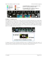
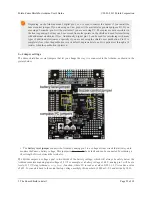
The Zumo shield has several jumpers that let you change the way it is connected to the Arduino, as shown in the
picture below.
• The
battery level jumper
connects the Arduino’s analog pin 1 to a voltage divider circuit that allows you to
monitor the Zumo’s battery voltage. This jumper is disconnected by default and can be connected by soldering a
short length of wire between the two holes.
The divider outputs a voltage equal to two-thirds of the battery voltage, which will always be safely below the
Arduino’s maximum analog input voltage of 5 V. For example, at a battery voltage of 4.8 V, analog pin 1 will be at a
level of 3.2 V. Using Arduino’s
analogRead()
function, where 5 V is read as a value of 1023, 3.2 V is read as a value
of 655. To convert it back to the actual battery voltage, multiply this number by 5000 mV×3/2 and divide by 1023:
Pololu Zumo Shield for Arduino User's Guide
© 2001–2013 Pololu Corporation
3. The Zumo Shield in detail
Page 25 of 38


