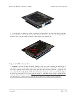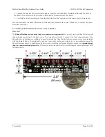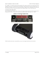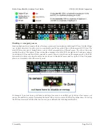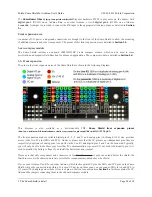
Now you effectively have a four-sensor array and analog pins A2 and A3 are available for general-purpose use. To
configure the ZumoReflectanceSensorArray library to use this new configuration, call
init
with these arguments:
byte pins[] = {4, 11, A0, 5};
reflectanceSensors.init(pins, 4);
Alternatively, you could make two ZumoReflectanceSensorArray objects, one for the two exterior sensors and
another for the two interior sensors, which might allow for cleaner code, but the drawback is that you can no longer
read all four sensors in parallel with this approach.
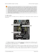
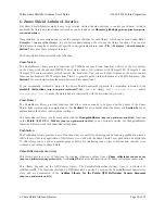
If you later decide you want to re-enable those sensors, you can connect across the cut trace with a wire, or you can
use a wire to remap the sensor to a different pin. The following example shows how you could re-enable the A2 sensor
and remap the A3 sensor to pin A5 instead:
To configure the ZumoReflectanceSensorArray library to use this remapped configuration, call
init
with these
arguments:
byte pins[] = {4, A5, 11, A0, A2, 5};
reflectanceSensors.init(pins, 6);
Or, if you are not using an I/O line to control the IR emitters:
byte pins[] = {4, A5, 11, A0, A2, 5};
reflectanceSensors.init(pins, 6, 2000, QTR_NO_EMITTER_PIN); // 2000 = timeout after 2 ms
Pololu Zumo Shield for Arduino User's Guide
© 2001–2013 Pololu Corporation
2. Assembly
Page 21 of 38

