Reference MVI56-DEM
♦
ControlLogix Platform
Honeywell DE Communication Module
ProSoft Technology, Inc.
Page 45 of 80
March 6, 2008
The read data block also contains the block identification code the module
expects to receive from the processor (word 1 in the block). Under normal data
transfer conditions, the ladder logic should use the code to build the appropriate
block for the module in the output image.
Write Block
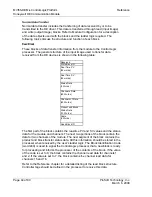
These blocks of data transfer information from the processor to the module. The
general structure of the output image used to transfer this data is shown in the
following table.
Write Block ID
Channel x Data
(17 Words)
Channel x+1 Data
(17 Words)
Channel x+2 Data
(17 Words)
Channel x+3 Data
(17 Words)
Channel x+4 Data
(17 Words)
Channel x+5 Data
(17 Words)
Channel x+6 Data
(17 Words)
Channel x+7 Data
(17 Words)
Spare Data
(111 Words)
The Block Identification code defines the content of the data contained in the
block. If the block code is set to 0, data for channels 1 to 8 are contained in the
block. If the block code is set to 1, data for channels 9 to 16 are contained in the
block. Under normal conditions, the value used for the write block identification
code should be that received in the read block from the module.
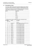
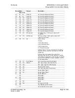
The Reference chapter of this document contains a detailed description of the
write block structure. Ladder logic should be written to transfer the correct write
data for each channel into these blocks.


