2/22/2018
ROBOTIS e-Manual
http://emanual.robotis.com/docs/en/dxl/x/xm430-w210/
20/34
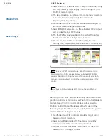
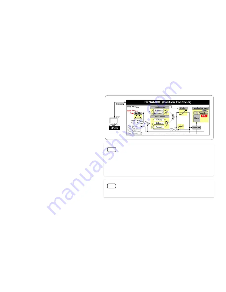
2. Goal Position(116) is converted to target position trajectory
and target velocity trajectory by Profile Velocity(112) and
Profile Acceleration(108).
3. The target position trajectory and target velocity trajectory
is stored at Position Trajectory(140) and Velocity
Trajectory(136) respectively.
4. Feedforward and PID controller calculate PWM output for
the motor based on target trajectories.
5. Goal PWM(100) sets a limit on the calculated PWM output
and decides the final PWM value.
6. The final PWM value is applied to the motor through an
Inverter, and the horn of Dynamixel is driven.
7. Results are stored at Present Position(132), Present
Velocity(128), Present PWM(124) and Present Current(126).
Note
In case of PWM Control Mode, both PID controller and
Feedforward controller are deactivated while Goal PWM(100)
value is directly controlling the motor through an Inverter. In this
manner, users can directly control the supplying voltage to the
motor.
Note
K
a
is an Anti-windup Gain that cannot be modified by
users.
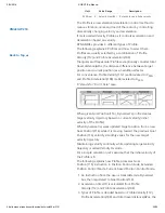
Below figure is a block diagram describing the current-based
position controller in Current-based Position Control Mode. As
Current-based Position Control Mode is quite similar to
Position Control Mode, differences will be focused in the
following steps. The differences are highlighted with a green
marker in the block diagram as well.
1. Feedforward and PID controller calculates target current
based on target trajectory.
2. Goal Current(102) decides the final target current by
setting a limit on the calculated target current.
3. Current controller calculates PWM output for the motor
based on the final target current.
Back to Top ▲


