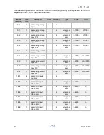
• -: no rule - no control rule set for this relay.
Press 5 to review the configuration and confirm to save it. When the new configuration is
saved, Arduino will automatically reset and restart with the new configuration.
The configuration is permanently stored in the Arduino’s EEPROM memory, and retained
across restarts and power cycles.
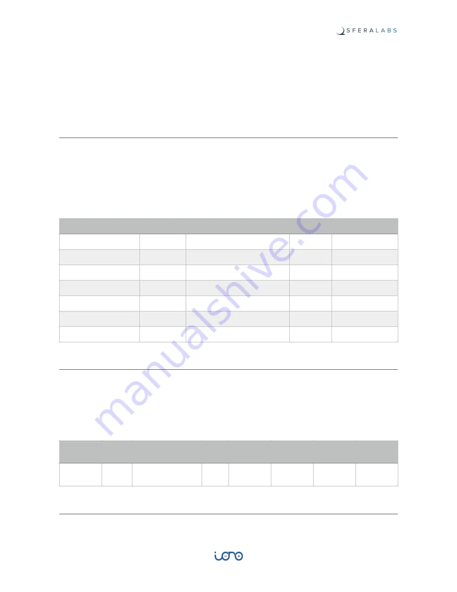
Modbus address tables and functions
Relays
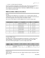
Use Modbus function Read Coils, at coil address 1 to 6, to read the status of the last
command given to the output relays. Because the relays are latching, the status will return
zero at boot, regardless of the actual position of the relays’ contacts.
Use functions Write Single Coil or Write Multiple Coils to control the relays output.
Analog (PWM) output
Use Modbus function Read Holding Registers at address 601 to read the status of the
analog output AO1. The returned value is in mV, so the value range is 0 to 10000.
Use function Write Single Register to control the voltage output of AO1.
Digital inputs
Digital inputs DI1 to DI6 can be read at two different address ranges, using function Read
Discrete Inputs.
Address (decimal)
Size (bit)
Description
R/W
Functions
1
6
command of output relays
r/w
1, 5, 15
1
1
command relay 1
r/w
1, 5, 15
2
1
command relay 2
r/w
1, 5, 15
3
1
command relay 3
r/w
1, 5, 15
4
1
command relay 4
r/w
1, 5, 15
5
1
command relay 5
r/w
1, 5, 15
6
1
command relay 6
r/w
1, 5, 15
Address
(decimal)
Size
(word)
Description
R/W
Functions
Type
Range
Unit
601
1
write analog voltage
output AO1
r/w
3, 6
unsigned
short
0 - 10000
V/1000
17
User Guide

