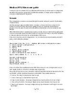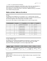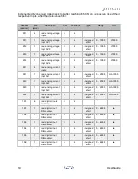
Reading addresses 101 to 106 returns the value of the input pins filtered with a de-bounce
function. This filter has a 50 ms time constant, so that a value change is reported only after
being stable for at least 50 milliseconds.
Reading addresses 111 to 116 returns the instantaneous value of the input pins, with no
de-bounce filter applied.
Analog inputs and digital counters
Use Modbus function Read Input Registers to read the values of analog inputs. Reading
addresses 201 to 204 returns the voltage on AV1 to AV4 in mV, from 0 to 10000. Reading
addresses 301 to 304 returns the current on AI1 to AI4 in mA/1000 (microAmperes), from 0
to 20000.
This sketch also implements counters on digital inputs. Reading input registers at address
1001 to 1006 returns unsigned short values from 0 to 65535. These counters are
Address (decimal)
Size (bit)
Description
R/W
Functions
101
6
read digital inputs (with de-
bounce)
r
2
101
1
read digital input DI1 (with de-
bounce)
r
2
102
1
read digital input DI2 (with de-
bounce)
r
2
103
1
read digital input DI3 (with de-
bounce)
r
2
104
1
read digital input DI4 (with de-
bounce)
r
2
105
1
read digital input DI5 (with de-
bounce)
r
2
106
1
read digital input DI6 (with de-
bounce)
r
2
111
6
read digital inputs (no de-bounce)
r
2
111
1
read digital input DI1 (no de-
bounce)
r
2
112
1
read digital input DI2 (no de-
bounce)
r
2
113
1
read digital input DI3 (no de-
bounce)
r
2
114
1
read digital input DI4 (no de-
bounce)
r
2
115
1
read digital input DI5 (no de-
bounce)
r
2
116
1
read digital input DI6 (no de-
bounce)
r
2
18
User Guide

