27
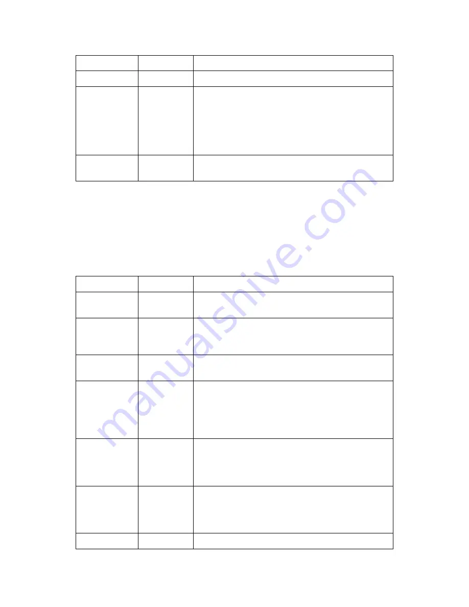
and “3” indicating a forced transmission.
Delta Time
1
Age in minutes of the most recent data
Data
3x num
sensors
Data in either interleaved, or non-interleaved
format. The example above shows the data
interleaved (most recent of all sensors followed by
next oldest, and so on). See the section below,
“Six-Bit Binary Encoded Format” for details on
how these values are encoded.
Battery
Voltage
1
Logger battery voltage measured just prior to
transmission
Pseudobinary-C Format
The Pseudobinary-C format also produces an ASCII report of 6-bit pseudo-binary formatted
values, but with additional fields to describe label and time information. Just as the “B” version
of the format, this format is “pseudo”-binary, because each sensor value and descriptor is
expressed in the range of ASCII characters, but not in such a way that is readily human-readable.
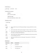
Pseudobinary-C Format
Name
Bytes
Description
Block ID
1
BLOCK-IDENTIFIER is always sent as "C" to
indicate that this is the pseudobinary C format.
Group ID
1
GROUP-ID can be "1" to indicate a scheduled
transmission, “2” meaning an alarm transmission,
and “3” indicating a forced transmission.
Measurement
Delimiter
1
This byte is always a “+” and it is used to denote
the start of measurement data.
Measurement
Index
(Sequence)
1
The Sequence number assigned by user in the
output telemetry settings. This value is encoded 6
bit binary. Typically, the sequence number assigned
is unique, allowing you to uniquely identify the
data point.
Day
2
This 2 byte encoded 6 bit binary encoded number
represents the Julian day of the year. The day tells
when the most recent (first) sensor reading of this
measurement was made.
Time
2
This 2 byte encoded 6 bit binary encoded number is
a number of minutes into the day. It tells when the
most recent (first) sensor reading of this
measurement was made.
Interval
2
This 2 byte encoded 6 bit binary encoded number


