Pulse Counting Mode
This operating mode puts the system into pulse count mode, where each channel will count the
number of pulses received on a given input channel.
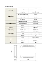
The system features a user-definable de-bounce period, which is factory set to 10mS, allowing for
pulses <100kHz. This de-bounce period can be reduced if the user can guarantee a solid state signal
(as opposed to relay contacts) and a good low electrically noisy environment.
On detection the channel total is incremented and this new value is immediately written to FRAM
non-volatile storage so as to reduce venerability to power outages.
The input counts are stored as 32bit unsigned integers giving maximum channel counts of
4,294,967,295.
The system can also be configured with per-channel counter offset values, allowing easy retrofitting
into existing environments; these offsets are stored in EEPROM again providing resilience against
power outage.
Whilst the values for current pulse count total and offset values are stored separately, these values
are added together and stored in the respective Modbus register.
This mode of operation is mutually exclusive to PWM measurement mode, i.e. the system cannot be
configured for mixed PWM and pulse count modes at the same time.
Static Level Mode
This is the most basic operating mode and puts the system into binary logic level indication. Voltage
inputs exceeding the high level threshold will show as logic level 1, and below the low threshold will
show as logic level 0, the logic state for voltages in-between are not guaranteed so should not be
relied upon.
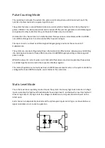
Each channel is independently isolated and the optocoupler inputs are AC type, as shown below, so
signal orientation is not crucial to operation.


