Tiger 320 Series Programming Code Sheet
Draft Copy. Code Version V3.08a
Texmate Inc. Tel. (760) 598 9899 • www.texmate.com
19
2 February, 2005 Prog. Code Sheet V3.08a (NZ101)
Commonly Used Registers
Note:
3-digit programming codes are specified within square
brackets [XXX]. If an X appears in the description of a
3-digit programming code or in a configuration proce-
dure, this means that more than one choice can be
made, or any number displayed in that digit is not rele-
vant to the function being explained.
Data
Source
for
Analog
Outputs
1 & 2
Data
Source
for
Setpoints
Reset
Dest.
Reset
Source
Data
Source
for
Totalizers
1 & 2
Register Functions
Register
Numbers
Data
Source
for
Displays
Data
Source
for
Peak &
Valley
Display [diSP]
-
●
●
●
●
Result [rESLt]
-
●
●
●
●
●
●
●
CH1 [Ch1]
-
●
●
●
●
●
●
●
CH2 [Ch2]
-
●
●
●
●
●
●
●
CH3 [Ch3]
-
●
●
●
●
●
●
●
CH4 [Ch4]
-
●
●
●
●
●
●
●
Total 1 [tot_1]
-
●
●
●
●
●
●
Total 2 [tot_2]
-
●
●
●
●
●
●
Peak [PEAK]
-
●
●
Valley [VALEY]
-
●
●
Tare [tArE]
-
●
PID Output 1
50
PID Output 2
51
Smart Result 1
54
Smart Result 2
55
Smart Result 3
56
Smart Result 4
57
Smart Result 5
58
Smart Result 6
59
Smart Result 7
60
Analog Output 1
83
Analog Output 2
84
Timer 1
95
Timer 2
96
Smart Reset Offset 1
121
●
Smart Reset Offset 2
122
●
Clock - Seconds
213
Clock - Minutes
214
Clock - Hours
215
Clock - Days
216
Clock - Date
217
Clock - Month
218
Clock - Year
219
Setpoint Latch
221
●
Relay De-energize
222
●
Zero Offset - Result
227
Zero Offset - CH1
228
Zero Offset - CH2
229
Zero Offset - CH3
230
Zero Offset - CH4
231
A Tiger 320 Series controller has 6,144 registers avail-
able for use by the meter’s operating system and the
Tiger Macro Development System (TDS).
See TDS Macro Tutorial (NZ212) for further information
on developing macros for Tiger 320 Series controllers.
40 Manually Selectable Registers
Using the front panel buttons, there are 40 registers that
may be selected for use within the following functions:
• [
CODE_1] - Display Configuration [X50]
. Select a
register as the data source for displays, peak and val-
ley, totalizers and analog outputs.
•
Setpoint Control Settings [X1X]
. Select a register as
the data source for a setpoint.
•
Setpoint Control Settings [XX7]
. Select a destina-
tion register that is reset by a setpoint with the con-
tents of a selected source register.
•
Setpoint Control Settings [XX7]
. Select the contents
of one register to be copied into another register by a
setpoint.
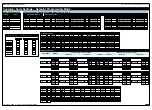
The 40 registers that can be selected as a data source,
a reset source, or a reset destination for the above func-
tions are shown in the table opposite.
This table shows, in seven columns, the functions where
these registers can be used.
Where a register is more likely to be used in a particular
function, a closed circle
●
is shown in the column. For
those functions where a register is less likely to be used,
an open circle
is shown.
No register number is shown in the table for the first 11
functions as these are identified on the display menu for
direct selection by their function names.
Beginning at [OFF] on the display, when selecting a reg-
ister as the data source, reset, or destination for a func-
tion, pressing the
button takes you through the numer-
ical register list beginning at register [1] and proceeding to
register [239] and then the named registers. Pressing the
button takes you in the reverse order starting at regis-
ter [DISP] and ending at register [1].
To cycle through the numerical register list quickly, keep
constant pressure on the
button. This increments one
register at a time until you reach register [10] then jumps
in increment blocks of 10 until you reach [100]. If you keep pressure
on the button you jump from register [100] to [200] and then stop
cycling. If the register you require is between [100] and [200] then stop
pressing the button at [100]. Resume pressing the button again and
the process is repeated, incrementing one register at a time until [10]
and then incrementing in multiples of 10 until you reach [200]. Repeat
this process for a number between [200] and [239].
Press the
and
buttons at the same time to take you directly back
to [OFF].
Registers that Should Not be Used
The following registers are contained within the selectable Register
Set, but they should not be selected because they are either
reserved for future use, or for use by the operating system only:
15, 38, 47, 48, 52, 53, 61-64, 123-128, 140, 141, 234-244
Selection of any of these registers may cause a malfunction.
[TOT_1]
[TOT_2]
[TARE]
[RESULT]
[CH1]
[CH2]
[CH3]
[CH4]
[DISP]
[ 1]
[ 2]
.....[ 10]
[ 11]
[ 12]
.....[ 20]
[ 100]
[ 200]
.....[ 239]
The
button takes you forward,
the
button takes you back.
[AUX_5]
[VALLEY]
[PEAK]
[AUX_4]
[AUX_3]
[AUX_2]
[AUX_1]
Constant pressure on the
button moves
thru Registers 1 to 239 one register at a time
until you get to ten, then it jumps in multiples
of 10, until you reach 100, then it jumps in
multiples of 100.
Stopping and starting again resumes single
steps forward.
Use the
and
buttons to cycle through
the Registers Menu and
Registers (1 to 239) to
select the data source
for displays, peak and
valley, totalizers and
analog output.


